TM 5-4310-452-14
5-21.
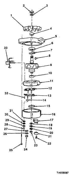
ALTERNATOR REPAIR (Con't).
a.
DISASSEMBLY
1.
Remove 2 screws (22), cover (21), and electric
brush holder assembly (17).
2.
Remove 4 screws (25) from rear housing (16) and
front housing (5).
CAUTION
When separating housings, do not
insert screwdrivers deeper than 0.063
in. (1.6 mm). Damage to the stator
windings may result.
3.
Separate rear housing (16) from front housing (5).
4.
Place rear housing (16), open end down, on clean
work surface.
5.
Remove 2 self-locking nuts (24), 2 flatwashers (26),
and insulators (27). Discard self-locking nuts.
6.
Remove nut (23), lockwasher (20), flatwasher (19),
and insulator (18). Discard lockwasher.
7.
Remove stator (11) and 2 semiconductor devices
(12 and 13) from rear housing (16).
8.
Remove 2 sleeves (32) and semiconductor device
(33).
9.
Remove spacer (28) and insulator (14).
NOTE
Tag and mark location of stator
electrical leads prior to removal.
10. Disconnect
stator
(11)
electrical
leads
from
semiconductor devices (12 and 13).
11. Remove nut (29), washer (30), and insulator (31).
Remove semiconductor device (33).
12. Remove preformed packing (15) from rear
housing (16). Discard preformed packing.
13. Using puller, remove bearing (10) from rotor
assembly (9).
5-48


