
1
Belt guard
11
Elbow, 90 std, 1 in. NPT
2
Screw, 3/16--32 x 1/2 in.
12
Exhaust tube, director-to-compartments
3
Lockwasher, 3/8 in. (3 rqr)
13
Elbow, 1/4 in. NPT
4
Cap screw, 3/8-16 x 1 in. lg (3 rqr)
14
Nipple, 1/4 in. NPT x 6 in.
5
Intercooler assembly
15
Coupling, 1/4 in. NPT
6
Cylinder head
16
Pipe plug, 1/4 in.
7
Elbow, 3/4 in.
17
8
Exhaust tube, engine-to-director
18
Exhaust tube, director-to-atmosphere
9
Aftercooler assembly
19
Hose reel
10
Exhaust director
Figure 33. Continued.
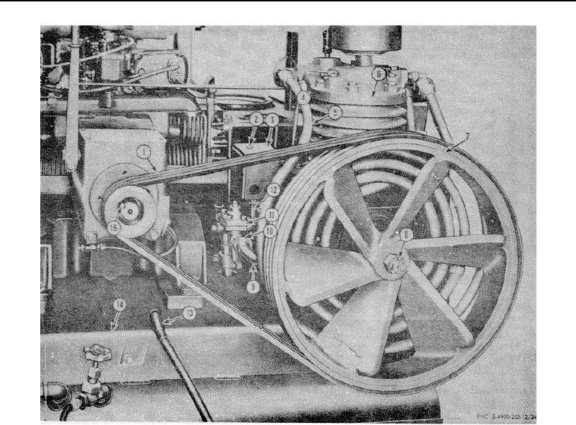
1
Drive belt (3 rqr)
5
Intercooler assembly
9
Aftercooler assembly
13
Battery ground cable
2
Cover screw
6
Cylinder head
10
Straight fitting, 34 in.
14
Mounting base
3
Pressure switch cover
7
Flywheel pulley
11
Control valve assembly
15
Drive pulley
4
Elbow, 3/4 in. (3 rqr)
8
Castellated nut
12
Nipple, Y4 x 51/2 in.
16
Key
Figure 34. Belts, flywheel, and pulley removal.
73