(2) Remove screws (1) securing mounting bracket
e. Installation.
(1) Position the trouble light assembly on the
(26) to the unit frame and remove the trouble light
unit frame and secure bracket (26) with screws (1).
assembly.
b. Disasssembly. Disassemble the trouble light as-
(2) Connect the power lead (50) and cable assem-
sembly in numerical sequence as illustrated in figure
bly (52) and ground lead (51) to wire assembly (53).
4-3.
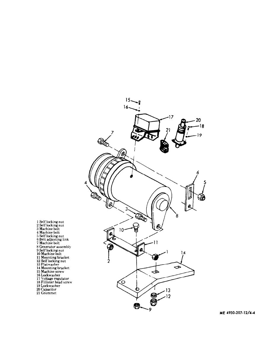
4-11. Generator and Voltage Regulator
c. Inspection and Repair.
a. Removal.
(1) Inspect all electrical leads for damaged insu-
(1) Tag and disconnect all electrical leads at the
lation.
voltage regulator.
(2) Inspect remaining parts for cracks, breaks, or
other damage.
(2) Refer to figure 3-2 and remove the generator
drive belt guard.
(3) Repair by replacement of defective parts.
(3) Remove the generator and voltage regulator
d. Reassembly. Reassemble the trouble light as-
assembly in numerical sequence as illustrated in
sembly in the reverse of numerical sequence as il-
figure 4-4.
lustrated in figure 4-3.
Figure 4-4. Generator and voltage regulator, removal and installation.
4-7


