lubricator frame.
(4) Attach a suitable lifting device to the four
(3) Connect the fuel filler cap chain and the static
lifting handles (10) and lift the enclosure assembly
wire at the fuel tank filler housing (fig. 1-2).
over the unit frame.
4-7. Battery and Battery Drawer
b. Disassembly. Disassemble the enclosure housing
a. Removal. Remove the battery and battery box
in numerical sequence as illustrated in figure 4-1.
in numerical sequence as illustrated in figure 2-3.
c. Reassembly. Reassemble the enclosure housing
b. Installation. Install the battery box and bat-
in the reverse of numerical sequence as illustrated
teries in the reverse of numerical sequence as illus-
in figure 4-1.
trated in figure 2-3.
d. Installation.
(1) Attach a suitable lifting device to the four
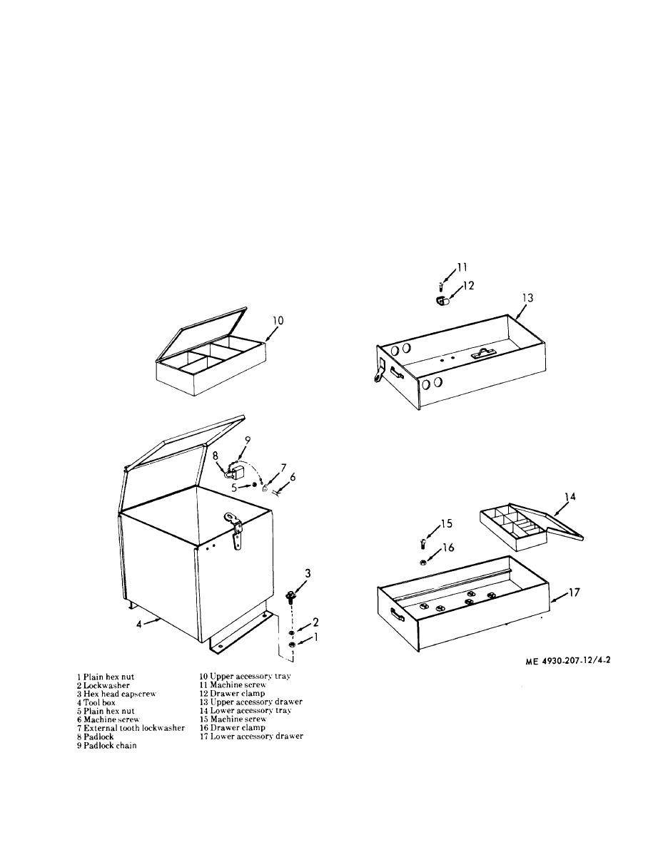
4-8. Tool Box and Accessory Drawers
lifting handles (10, fig. 4-1) and install the enclosure
a. Removal. Remove the tool box and accessory
assembly over the lubricator frame.
drawers in numerical sequence as illustrated in fig-
(2) Install four lifting ring washers (2) and lifting
ure 4-2.
rings (1) and secure the enclosure assembly to the
Figure 4-2. Tool box and accessory drawer, removal and installation.
4-5


