TM 5-4930-218-14
(e) Repeat action until fluid has replaced air
(1) Jack up the wheel and block under the frame
in system, then close valve; remove hose.
so that the wheel is off the ground,
(f) Refill master cylinder with brake fluid.
(2) Rotate the wheel and, while it is rotating,
(g) Repeat the above operation on the other
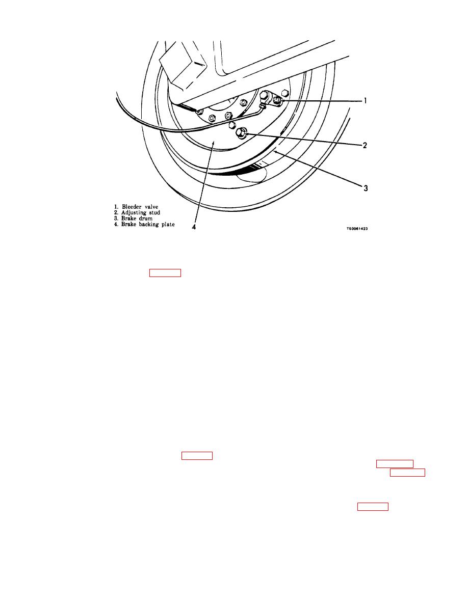
turn the adjusting stud (2, fig. 4-24) counterclockwise
wheel cylinders.
until the brake starts to drag against the drum,
slowing the rotation of the wheel. Back off the ad-
CAUTION
justing stud to relieve the drag.
Maintain a high level of fluid in the
(3) Rotate the wheel again and turn the second
master cylinder while bleeding each
adjusting stud counterclockwise until the brake
wheel cylinder.
starts to drag against the drum, slowing the rotation
(3) Pressure feed filler bleeding.
of the wheel. Back off the adjusting stud just enough
to relieve the drag.
(a) Remove the drain tube from the master
(4) Repeat the procedure on the opposite wheel.
cylinder.
b. Bleeding.
(b) Connect the hose to pressure feed filler,
(1) General. You will have to bleed air from
with the proper size adapter, to the opening of the
hydraulic portion of service brakes if the system is
master cylinder.
opened or a component of the system has been
(c) The filler should contain from 10 to 20 psi
replaced.
air pressure and sufficient fluid to maintain constant
(2) Manual bleeding.
fluid level in the master cylinder.
(a) Connect trailer service brake hoses to a
towing vehicle for manual bleeding as the brake
subparagraph (2) above.
pedal must be pressed and released to actuate the
(e) Replenish the fluid in the master cylinder
system. You must keep the master cylinder full of
after bleeding, if necessary. Refer to the LO 5-4930-
218-12.
brake fluid or air will enter the system.
c. Brake Removal and Disassembly.
clean cloth. Attach a tube to the bleeder valve and
(1) Remove the wheel and tire (para 4-57).
(2) Remove the wheel hub and drum (para 4-58).
place other end of tube in a suitable container.
(c) Fill the master cylinder with brake fluid.
(3) The wheel brake can be removed as an assem-
Refer to LO 5-4930-218-12.
bly or it can be disassembled while on the vehicle. To
remove it as an assembly, disconnect the hydraulic
(d) Pump brake pedal on towing vehicle until
lines to the wheel cylinder (42, fig. 4-25) and remove
pressure is applied. Hold pedal pressure and open
the cap screws (46) that secure the backing plate (57)
bleeder valve until pressure is released on pedal, then
close valve.
to the axle.


