TM 5-4930-218-14
bearing cones and rollers in the crankcase.
pits, or burned surfaces. Replace defective bearing
(4) Install the centrifugal unloader (para 7-6). Be
cups.
sure you adjust crankshaft end play when installing
(6) Inspect the crankcase for breaks, cracks,
the unloader.
chips, or other defects. Replace if defective.
(5) Install pistons, piston rings, connecting rods,
c. Reassembly and Installation.
and cylinder block (para 7-8).
(1) Use a suitable bearing cup driver to press the
(6) Install handhole plate and new plate gasket
(7) Install the oil drain plug in the crankcase.
bearing cup in the governor housing (35) in the same
(8) Install flywheel (para 7-2).
manner.
(9) Install compressor (para 4-42).
(2) Press the tapered bearing cones and rollers
(10) Install tube assemblies (para 4-46).
(12, fig. 7-3) on the crankshaft (13), You should make
certain that cones and rollers are seated firmly
against the crankshaft shoulders to insure a correct
reading when determining crankshaft end play.
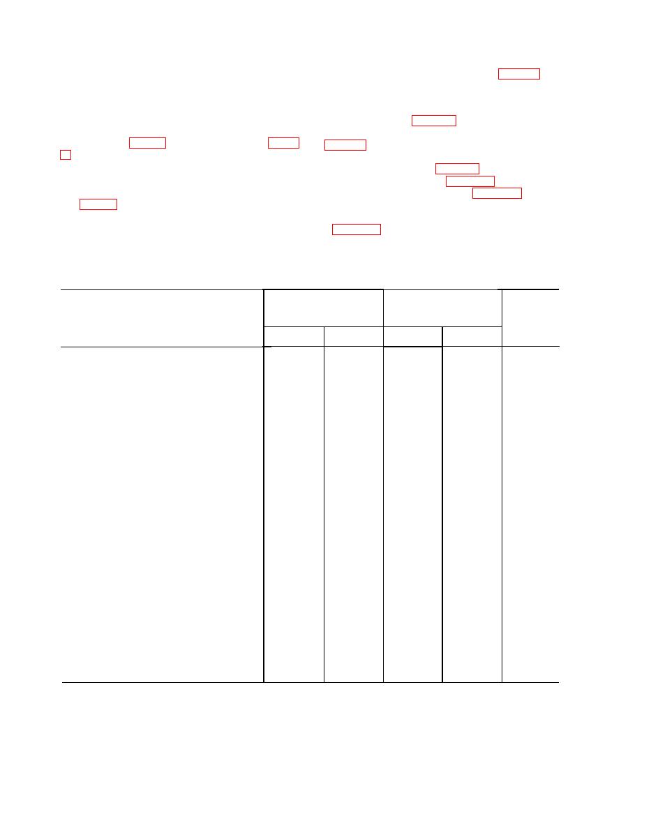
desired clearances, and maximum allowable wear and
clearances.
(3) Install the assembled crankshaft and tapered
Manufacturer's dimensions
Desired
Maximum
and tolerances
clearance
allowable
in inches
Points of measurement
wear and
clearance
Min.
Max
Min.
Max.
Cylinders:
0.0060
Bore, low preasure. . . . . . . . . . . . . . . . . . . . . .
4.6250
4.6250
0.0020
0.0030
0.0060
............ ..........
Bore, high pressure. . . . . . . . . . . . . . . . . . . . . . .
2.5000
2.5005
Taper . . . . . . . . . . . . . . . . . . . . . . . . . . . . . . . . . . .
0.0010
0.0010
0.0020
............ ...........
Out-of-round ... . . . . . . . . . . . . . . . . . . . .
0.0010
0.0010
Crankshaft:
1.3760
1.3770
Journal size, main bearing. . . . . . . . . . . . . . . . . . .
1.6230
1.6250
Journal size, connecting rod. . . . . . . . . . . . . . . .
0.0005
Journal out-of-round. . . . . . . . . . . . . . . . . . . .
Journal taper. . . . . . . . . . . . . . . . . . . . . .
0.0002
Pistons, piston pins, piston rings:
0.0015
Piston size, low pressure. . . . . . . . . . . . . . . . .
4.6200
............
...........
4.6195
2.4970
2.4975
0.0015
...........
............
Piston size, high pressure . . . . . . . . . . . . . . . .
.......
Piston pin diameter, low pressure. . . . . . . . . .
0.8125
0.0010
0.8122
..........
.....
0.0010
0.8122
............
Piston pin diameter, high pressure. . . . .
0.8125
Piston pin length, low pressure. . . . . . . . . . . . . . .
2.1250
2.1350
0.0002
0.0009
2.1250
2.1350
0.0009
0.0002
Piston pin length, high pressure. . . . . . . . . . . . . .
............
0.0009
. . . . . . ...
0.0002
Piston pin clearance in piston. . . . . . . . . . . . . . . .
Piston-to-cylinder clearance,
0.0055
............ ...........
0.0054
low pressure . . . . . . . . . . . . . . . . . . . .
Piston-to-cylinder clearance,
0.0030
............ . . . . . . . . . .
0.0025
high pressure . . . . . . . . . . . . . . . . . . . . .
Piston ring side clearance,
.........
0.0025
. . . . . . . . . . . . 0.0010
low pressure . . . . . . . . . . . . . . . . . .
Piston ring side clearance,
0.0010
... . . . . . . . . .
high pressure. . . . . . . . . . . . . . . . . . . . . . . . . .
..........
0.6045
Piston ring gap, low pressure. . . . . . . . . . . . . . . . .
0.0130
0.0230
Piston ring gap, high pressure. . . . . . . . . . . . . . . . . .
0.0170
0.0070
Connecting rods and journals
. . . . . . . . . . . 0.0003
Bearing running clearance . . . . . . . . . . . . . . .
............
0.0016
.......
Bearing side clearance. . . . . . . . . . . . . . . . . . .
. . . . . . . . . . . . 0.0040
0.0012
1.3760
1.3770
Bearing internal diameter . . . . . . . . . .
1.6270
1.6283
Rod internal diameter (cold) . . . . . . . . . . . . . . .


