
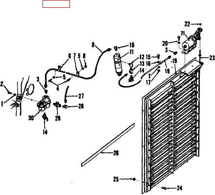
(3) Disconnect the air line (18) from shutterstat to air cylinder and the tee (13) at the side of the shutterstat.
(4) Unscrew the shutterstat (11) from the water pump inlet connection and remove the elbow (12), tee (13) and
drain cock (14) from the shutterstat outlet opening.
b. Installation.
(1) Assemble the elbow (12, fig. 25), tee (13) and drain cock (14) to the shutterstat (11), and screw the
shutterstat down into the opening in the water pump inlet connection.
1
Lockwasher, 1/4 (2 req)
17
Nut, hex 1/4-20 (1 req)
2
Cap screw, 1/4-20 x 5/8 (2 req)
18
Air line, 1/4 x 40
3
Connector, 1/4 x 1/8 M (2 req)
19
Shutter assembly
4
Bolt, hex hd, 5/16-18 x 1/2 (2
20
Bolt, hex hd, 5/16-18 x 5/8 (2
req)
req) and washer
5
Lockwasher, 5/16 (4 req)
21
Air cylinder
6
Clamp
22
Nut, hex, 4-28 (1 req)
7
Clamp
23
Control rod
8
Nut, hex, 5/16-24 (1 req)
24
Bolt, hex hd, 5/16-18 x (6
9
Air line, 1/4 x 50
req)
10
Elbow, 1/4 x 1/8 M x 90
25
Nut, special (6 req)
11
Shutterstat
26
Packing
12
Elbow 1/8 M x 1/8 F x 90
27
Air line, 5/16 x 30
13
Tee, 1/8 M x 1/8 F x 1/4
28
Elbow, 5/16 x 1/8 M x 90
14
Drain cock (2 req)
29
Shutoff cock
15
Cap screw, 1/4-20 x 1/2 (1 req)
30
Air filter
16
Clamp
Figure 25. Exploded view of radiator shutter and controls.
70