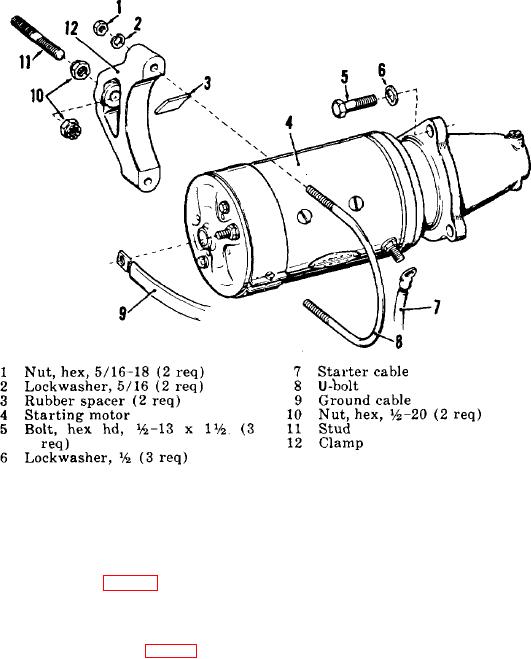
motor housing and the clamp (12) and install the U-bolt (8), lockwashers (2) and hex nuts (1), tightening the hex nuts
finger tight.
(2) Aline the three holes in the motor mounting flange with those in the rear engine support, and install the hex
head bolts (5) and lockwashers (6). Tighten the bolts (5) and the hex nuts (1) securely.
(3) Connect the starter cable (7) and ground cable (9) to the starting motor terminals.
Figure 34. Exploded view of starting motor and attaching parts.
94. Starting Motor Brushes
a. Removal. Remove the cover band screw and nut and slip the cover band from the commutator-end frame to
expose the starting motor brushes (fig. 35). Raise the loop of the brush tension spring until a pin or short length of stiff
wire can be passed through the loop to support it above the inspection opening. Remove the brush screw and lockwasher
and lift the brush from the holder.
b. Installation. Install a new brush (fig. 35) in the brush holder, remove the pin or wire, and allow the loop of the
tension
90

