
(5, fig. 40) over the ammeter terminals. Install the mounting washers and nuts. Connect the leads according
to the tags placed on the ammeter at removal.
b. Temperature Gage.
(1) Removal. Remove the water temperature gage bulb from the exhaust manifold (8, fig. 55). Remove the
three clamps (24, fig. 39) from around the temperature gage flexible tube, and slip the flexible tubing out of
the clamps. Do not allow the tubing to kink. Remove the. nuts and lockwashers holding the water
temperature gage mounting bracket (1, fig. 40), and pull the water temperature gage (23, fig. 39), together
with the bulb and flexible tubing, from the front of the panel.
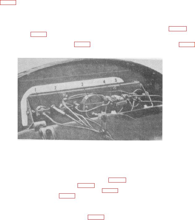
1 Water temperature gage mtg
3 Air pressure gage mtg bracket bracket
bracket
4 Hourmeter mtg
2 Oil pressure gage mtg bracket
5 Ammeter mtg bracket
Figure 40. Rear -view of installed instrument panel.
(2) Installation. Place the water temperature gage (23, fig. 39) in position in the panel, and place the
temperature gage mounting bracket (1, fig. 40) over the gage studs. Install the mounting washers and
nuts. Slip the flexible tube into the three clamps (24, fig. 39) and tighten the clamps. Install the temperature
bulb in the exhaust manifold (8, fig. 55).
c. Oil Pressure Gage.
(1) Removal. Disconnect the tube assembly (21, fig. 39) coupling (15) and connector (32) at the rear of the oil
101