
cylinder two, cylinder four and cylinder three, in that order.
f. After all valves have been checked and adjusted, install the cylinder head cover and gasket (par. 119c).
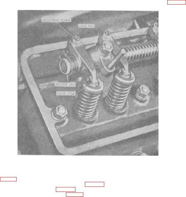
Figure 56. Valve clearance adjusting screws.
122. Engine Cylinder Head and Valves
a. Removal (fig. 57).
(1) Remove the cylinder head cover and gasket (par. 119a).
(2) Remove the engine manifolds (par. 120a).
(3) Remove all spark plugs and cables (par. 96).
(4) Disconnect the tube assembly (3) from the elbow (4) in the aftercooler end of the cylinder head (17).
(5) The engine cylinder head is mounted on 17 studs in the crankcase. Four of these studs protrude up through
the rocker arm brackets (8); five studs are located in line with the valve springs (10); the remaining
129