
eight studs are located in line with the spark plug openings. Remove the hex nuts (14) and the special
washers (13) from all studs. Lift the rocker arm assembly from its four mounting studs and remove the eight
push rods (24). Lift the assembled cylinder head and valves straight up from the studs and place it on a
clean working surface.
(6) Remove the cylinder head gasket (18) from the studs. If there is any doubt as to the serviceability of the
gasket, it must be discarded and replaced.
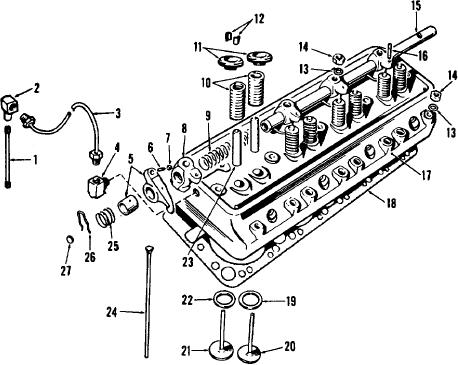
1 Nipple
15
Rocker arm shaft
2 Elbow
16
Stud (4 req)
3 Tube assembly
17
Cylinder head
4 Elbow
18
Cylinder head gasket
5 Rocker arm assembly (8 req)
19
Intake valve insert (4 req)
6 Adjusting screw (8 req)
20
Intake valve (4 req)
7 Nut, hex, 3/8-24 (8 req)
21
Exhaust valve (4 req)
8 Rocker arm bracket (4 req)
22
Exhaust valve insert (4 req)
9 Spacer spring (3 req)
23
Valve stem guide (8 req)
10 Valve spring (8 req)
24
Push rod (8 req)
11 Valve rotator (8 req)
25
End spring (2 req)
12 Spring lock retainer (16 req)
26
Spring retainer (2 req)
13 Washer, special (17 req)
27
Expansion plug, 3/4 (2 req)
14 Nut, hex 1/2-20 (17 req)
Figure 57. Exploded view of cylinder head and valves.
130