
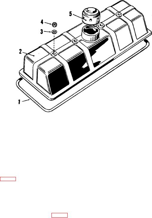
1 Cover gasket, 5/8-inch thick
4 Nut, hex 3/8-24 (4 req)
2 Cylinder head cover
5 Crankcase breather
3 Plain washer, 3/8 (4 req)
Figure 54. Exploded view of cylinder head cover and gasket.
b. Cleaning and Inspection. Clean the crankcase breather with compressed air. Wipe the cylinder head cover with a
cloth dampened in cleaning solvent. If the gasket has been damaged during removal of the cover, it must be replaced.
Blow all loose dirt away from the cylinder head valves with compressed air. Wipe grit from surface of head with a cloth
dampened in cleaning solvent.
c. Installation (fig. 54). Apply a light coat of gasket cement to the gasket surfaces of the cylinder head and cylinder
head cover. Carefully position the gasket (1) around the cover mounting surface of the cylinder head. Install the cylinder
head cover on the four mounting studs and fasten securely with the plain washers (3) and hex nuts (4). Install the
crankcase breather (5) and twist it counterclockwise to lock it in place.
120. Engine Manifolds
a. Removal and Disassembly.
(1) Unscrew the exhaust nipple (2, fig. 55) and weather cap (1) from the exhaust manifold (8).
125