
discharged through two tube assemblies. One tube leads to the oil filters; the other tube leads to the crankcase when oil is
delivered to the front camshaft bearing support and hollow camshaft. The main bearings are lubricated with oil through
passages to the camshaft bearings. The connecting rod bearings are connected by oil passages in the crankshaft to the
main bearings. The accessory drive is lubricated by means of oil flow through a tube assembly from the tappet chamber.
Oil is supplied intermittently to the engine cylinder head through a tube assembly from the rear camshaft bearing support.
e. The gear cover assembly encloses the front of the crank case. The accessory drive components are mounted to
the gear cover assembly.
214. Engine-Compressor Removal
a. Removal from Truck. Remove the hood top door (6, fig. 61). Remove the nuts, vibration dampeners, and washers
that fasten the engine-compressor to the mounting springs on the truck frame. Refer to paragraph 231. Insert a lifting
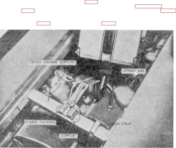
hook in the lifting bail (fig. 95) and lift the engine-compressor from the truck frame. Remove the housing (par. 128) before
proceeding with engine-compressor disassembly.
b.
Removal from Frame (fig. 96). Remove the radiator and fan (par. 88a). Remove the cotter pins (8) and
Figure 95. Lifting the engine-compressor.
217