TM 9-4310-397-14
(b)
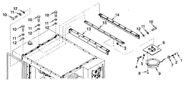
Unplug single circuit connector (Figure 4-14, 1) and housing tab (2).
1
Remove four self locking nuts (3), pan head screws (4), flat washers (5) and mounting plate (6). Discard
self locking nuts.
2
Remove grommet (7).
3
Drill out three rivets (8) from dome light (9).
Figure 4-14. Cover Panel Angles and Dome Light
(c)
Remove twenty six cap screws (10), lock washers (11), and flat washers (12) from two cover panel angles (13)
and (14) and one cover panel channel (15). Discard lock washers.
(d)
Remove three hex washer head screws (Figure 4-15, 1) and access door (2).
NOTE
Gaskets are glued to panels and must be replaced if removed.
(e)
Remove gaskets (3) and (4).
(f)
Disassemble bail handle stud (5) by removing retainer (6).
NOTE
Insulation has an adhesive backing and must be replaced if removed.
(g)
Remove clips (7) as necessary to remove insulation (8), (9), and (10) from panel (11). Discard clips.
(h)
Drill out rivets (12) and receptacle (13).
4-69