TM 9-4310-397-14
6-11. CRANKSHAFT, PULLEY, IDLER GEARS, AND MAIN BEARINGS INSPECTION, REPAIR AND
REPLACEMENT. - Continued
(b)
Remove main bearing caps.
NOTE
Visually inspect condition of bearing inserts as bearing caps are removed. Keep
caps and inserts together and in correct order.
(c)
Check main bearing clearance.
1
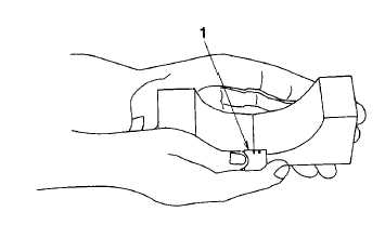
Place a strip of bearing clearance gauge (items 21, 22, and 23, section II, appendix E) (Figure 6-98,
1) in the center of the main bearing cap about three-fourths of the width of the bearing.
Figure 6-98. Main Bearing Clearance
2
Use oil on bearing clearance gauge to prevent smearing.
3
Install cap and torque to 85 ft-lb. (120 Nm).
NOTE
The use of bearing clearance gauge will determine wear, but will not determine
condition of either bearing or journal.
4
Remove cap and compare width of bearing clearance gauge with scale provided to determine
clearance. Maximum permissible clearance 0.006 in. (0.15 mm).
(2)
Remove crankshaft.
WARNING
Do not attempt to remove crankshaft by hand. Use proper lifting equipment to
avoid personal injury and damage to equipment.
(a)
Attach a nylon sling (or other suitable lifting sling) to journals of crankshaft (Figure 6-99, 1).
6-82


