TM 9-4310-397-14
6-11. CRANKSHAFT, PULLEY, IDLER GEARS, AND MAIN BEARINGS INSPECTION, REPAIR AND
REPLACEMENT. - Continued
(4)
Remove crankshaft gear.
(a)
Inspect gear for wear or damage.
(b)
If gear removal is required, pull gear with gear puller.
(c)
Remove Woodruff key from crankshaft if crankshaft requires reconditioning.
b.
Inspection.
(1)
Inspect crankshaft.
(a)
Clean crankshaft using solvent and compressed air.
(b)
Inspect oil passages to make sure they are open. Use compressed air and a small piece of wire.
(c)
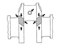
Inspect crankshaft for any signs of load stress, cracks, scoring, or scratches on journals. An inspection
must be made if the crankshaft damper was found to be damaged or defective. Figure 6-101 shows
critical areas of load stress in a crankshaft.
Figure 6-101. Inspect Crankshaft
(d)
When inspecting crankshaft for cracks, a method (such as the Fluorescent Magnetic Particle Method if
available) must be used that is capable of detecting minute cracks that are not visible to the eye. This
method magnetizes the crank, employs magnetic particles which are fluorescent and glow under black
light. Replace crankshaft if cracks are found. The crankshaft must be de-magnetized after the test.
(e)
Check each journal for evidence of excessive overheating or discoloration. If either condition exists,
replace crankshaft since heat treatment has probably been destroyed.
(2)
Measure assembled ID of bearings and OD of crankshaft journals.
(a)
With crankshaft out of cylinder block, install main bearing inserts and caps (be sure inserts are installed
correctly).
(b)
Torque main bearing cap screws to 85 ft-lb (120 Nm).
(c)
Measure ID of all bearings with an inside micrometer. ID of assembled insert should be 3.12 - 3.127 in.
(79.39 - 79.44 mm). See Figure 6-102.
6-84


