
TM 5-4310-354-14
1.
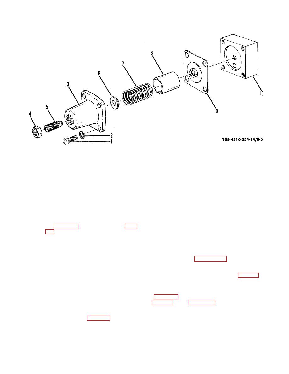
Cap screw (4)
6. Spring seat
2.
Lock washer (4)
7. Regulator spring
3.
Housing
8. Spring tube
4.
Nut -
9. Diaphragm assy
5.
Adjusting screw
10. Regulator base
Figure 6-5. Air pressure regulator assembly, disassembly and reassembly.
(1) Remove four cap screws (1), four lock
(a) Position diaphragm assembly (9) on
washers (2), and housing (3). Remove
regulator base (10) with holes
nut (4) and adjusting screw (5).
aligned and spring guide portion of
diaphragm assembly away from
(2) Remove spring seat (6), regulator sprin g
base.
(7), spring tube (8), and diaphragm
(b) Assemble spring tube (8), regulator
assembly (9) from regulator base (10).
spring (7), and spring seat (6).
(c) Place housing (3) over these
b. Cleaning, Inspection, and Repair.
assembled parts, press down on
housing (3) to seat against base
(1) Clean parts, except diaphragm assembly
(10). Attach housing (3) to base
(9, figure 6-5), in accordance with para
(10) with four lock washers (2) and
5-7.f.
four cap screws (4).
(2) Wipe diaphragm assembly (9) clean with a
(d) Install adjusting screw (5) and nut
clean, lint-free cloth.
(4).
(3) Inspect diaphragm assembly (9) for any
(e) Test and adjust the air pressure
cuts, tears, deterioration, or any other
regulator
in
accordance
with
defect.
(4) Inspect spring (7) for broken coils,
deformation, or any other defect.
(2) Reassemble air pressure regulator on
(5) Inspect all parts for cracks, breaks,
blowdown valve assembly (para 6-6.d).
damaged threads, or any other defect.
(6) Replace all defective parts.
d. Testing and Adjustment.
After installing air
pressure regulator on unit, check air line connections
c. Reassembly.
(1) Reassemble the air pressure regulator
pressure regulator as follows:
assembly in the reverse numerical
sequence shown in figure 6-5 as follows:
6-9

