• Home
  • Download PDF
  • Order CD-ROM
  • Order in Print
Figure 6-56.  Idler Shaft Removal
Figure 6-59.  Oil By-pass Valve

TM-9-4310-397-14 Compressor Unit Reciprocating 10 CFM 175 PSI Diesel Engine Driven Trailer Mounted Model CUE67-6DY-TM Manual
Page Navigation
  298    299    300    301    302  303  304    305    306    307    308  
TM 9-4310-397-14 6-9. CAMSHAFT.  AND TIMING GEAR TRAIN.  - Continued Figure 6-57.  Front Plate Studs (c) Replacement plate may have a bushing installed that may have to be removed.  Compare bore to old front plate. (d) Install upper and lower idler shafts by pressing shaft (Figure 6-58, 1) and thrust washer (2) in place in front plate. Figure 6-58.  Front Plate
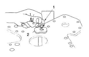
 (e) Install oil by-pass valve (Figure 6-59, 1) and spring (2). 6-50


Western Governors University

Privacy Statement
Press Release
Contact

© Copyright Integrated Publishing, Inc.. All Rights Reserved. Design by Strategico.