
the spring retainer, pump shim, guide, pump ball, relief
valve seat, strainer retainer, strainer spring, strainer
assembly, cap, connector, fourth stage plug, packing,
and crankcase.
Repair parts are included in the
crankcase repair kit.
31. Removal
Note. Prior to removal of the compressor group, clip
and remove all lock wire and drain the oil sump.
a. Remove the fan guard section (par. 25a) and
intercooler and aftercooler section (par. 27a).
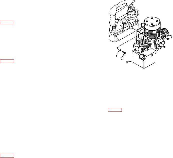
b. Remove the four machine bolts (2) and four
washers (1) and remove the compressor assembly (3)
from the gasoline engine.
32. Third Stage Section Disassembly
a. Unscrew the second stage relief valve (17) and
elbow fitting (13) from the head assembly (14).
1 Washer
2 Machine bolt
b. Unscrew the four screws (16) and washers (15)
3 Compressor assembly
and remove the head assembly (14).
Figure 10. Removing compressor group, exploded view.
c. Remove the gaskets (11 and 12), discharge
valve spring (10), and the discharge valve (9) from the
plunger assembly (18) from the crankcase.
valve plate (8).
c. Remove the three rings (16) from the plunger
d. Remove the valve plate (8), gasket (7), inlet
subassembly (17).
valve (6), and inlet valve spring (5) from the cylinder and
plunger assembly (4).
34. First Stage Valve Disassembly
e. Remove the cylinder and plunger (4) from the
crankcase and remove the spacer (3), shim (2), and
a. Unscrew and remove the elbows (8) from the
preformed packing (1).
head assembly (7). Remove the four screws (19) and
Note. The cylinder and plunger are matched parts.
washer (20) and remove the cap (21)
Do not separate the cylinder and plunger or mix with
b. Remove the filter cap (22) from the head
similar components of other compressors.
assembly (7). Remove the preformed packing (23) from
f. Unscrew the four screws (22) and washers (20)
the filter cap.
and remove the plug (19).
c. Remove the filter assembly (24) from the head
g. Remove the preformed packing (18) from the
assembly (I7).
plug (19).
d. Unscrew the six screws (5) and washers (6)
33. Second Stage Section Disassembly
and remove the valve and head assembly from the valve
plate (15). Remove the preformed packing seal (11)
a. Unscrew and remove the elbows (3 and 4) from
from the head assembly (7).
the head assembly (5); unscrew the four screws (1) and
e. Straighten and remove the cotter pin (18).
washers (2) then remove the head assembly.
Unscrew the nut (9) and washer (10) and remove the
b. Remove the gaskets (6 and 7), spring (8), valve
screw (17), gasket (16), seat (14), valve (13), and spring
(9) from the valve plate (10). Remove the valve plate,
(12) from the head assembly (7).
valve (11), spring (12), spacers (13 and 14), shim (15),
and the
AGO 5548A
20