
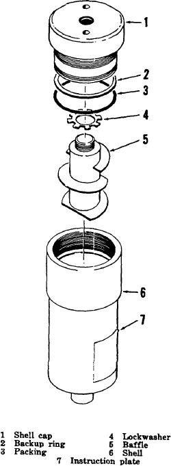
Figure 3-1. Moisture separator assembly, exploded view.
Section II. COMPRESSOR ASSEMBLY
and breather section.
The compressor assembly
3-4.
Description
sections are joined together to form a single working unit.
The first, second, and third stage cylinder sections are
The basic compressor assembly has five
assembled to the endbell, master rod, and shaft section.
different sections. These sections are the third stage
Within the crankcase of the endbell, master rod, and
section; second stage section; first stage section;
shaft section is assembled the oil reservoir and
endbell, master rod, and shaft section; and oil reservoir
15