
*TM 3-1040.244-34
c.
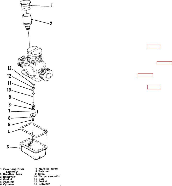
Disassembly.
(1) Pull cover and filter assembly (1) from
over breather body (2).
(2) Unscrew
breather
body
from
(3) Remove gasket (4).
Remove two
screws (7) attaching cylinder (6).
Remove cylinder and packing (5).
(4) Cut wire and remove retainer (8), shim
(9), piston assembly (10), ball (11),
socket (12), and retainer (13) from
connecting rod (8, fig. 3-7).
d.
Assembly.
(1) Install parts of oil pump piston repair kit
on connecting rod (8, fig. 3-7) and
secure with wire. Carefully guide end
of oil pump piston into bore of oil pump
cylinder (10, fig. 3-3) positioning gasket
(4) on oil reservoir (3).
Secure
reservoir with 14 screws and nuts.
(2) Install packing (5, fig. 3-3) in groove on
end of cylinder (6) and position both
parts in counterbore inside oil reservoir
(3). Secure parts to reservoir with two
screws (7).
(3) Screw breather (2) into crankcase.
Install cover and filter assembly (1).
3-12.
First Stage Section
a. Description.
The first stage section
consists of an elbow, gaskets, cylinder head, valve stop,
valve spring, valve plate, exhaust valve, intake valve,
cylinder and piston assembly, and attaching hardware.
The first stage cylinder is provided with a cover and air
cleaners which remove particles of foreign matter from
the ambient air drawn into the compressor. Additional
filtering is provided by a strainer and relief valve
assembly installed in the inlet port of the second stage
cylinder. Fine mesh screens installed in the body of the
strainer and relief valve assembly trap solid particles in
the interstage air, and spring-loaded poppets function as
pressure relief valves to prevent interstage air pressures
from exceeding predetermined values. The intake and
exhaust valves used in the first stage of the air
compressor are spring steel flapper-type valves mounted
Figure 3-3. Oil reservoir-and-breather section, exploded
on opposite sides of a valve plate installed between the
view.
cylinder head and the cylinder. The valves are spring
19