
Note.
The
cylinder-and-piston
assembly is made up of matched
parts. Do not attempt replacement of
individual parts.
c. Disassembly.
(1) Remove breather assembly (para 3-11c).
(2) Remove four machine screws (2) and
lockwashers (3) attaching cylinder
head (5) to cylinder-and-piston
assembly (20).
Remove cylinder
head.
(3) Unscrew and remove nut (1) and
lockwasher (4) from cylinder head.
Pull screw (14) from cylinder head (5)
and remove spring (12), valve (11),
valve plate (10), valve (9), valve spring
(8), and valve stop (7).
(4) Remove packing (6 and 13).
(5) Remove four nuts (15) and carefully
pull cylinder-and-piston assembly (20)
from crankcase.
(6) Remove snapring (17) from each end
of wristpin (16).
(7) Slide wristpin from piston and rod,
releasing piston. Remove piston.
Note.
The
cylinder-and-piston
assembly consists of matched parts.
Keep parts together and separate from
similar
assemblies
of
other
Scribe small marks
inside skirts to identify side of piston
that was toward fan end of crankcase.
Do not use pliers; use driftpin to
remove wristpin (16).
(8) Remove gaskets (18 and 19). Record
thickness of gasket combination and
discard.
Note. The gaskets used between the
cylinder-and-piston assembly and the
crankcase serve as shims to obtain
proper
piston-head-to-valve-seal
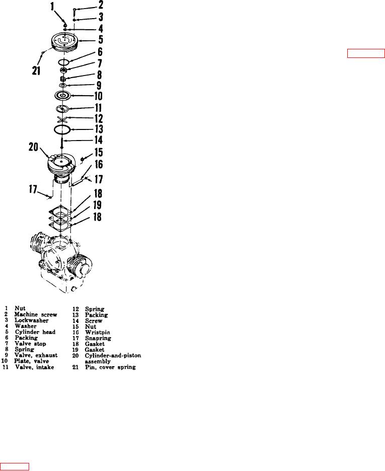
Figure 3-4. First stage section, exploded view.
clearance. The number of gaskets used
will vary with each cylinder.
By
are spring loaded to seat against concentric rings of
measuring the thickness of removed
holes which are drilled through the valve plate and
gaskets and adding 0.005 inch for each
coincide with the inlet and outlet ports in the cylinder
new paper gasket to allow for crush at
head.
installation, new gaskets required to
obtain proper clearance can be selected
b.
Maintenance. Overhaul of the first stage
with ease during reassembly.
section (fig. 3-4) is accomplished by replacing the intake
d.
Assembly.
valve spring, intake valve, exhaust valve, valve stop,
(1) Install steel gasket (19) flanked by
cover spring pin, gaskets, wristpin, retaining ring,
cylinder-and-piston assembly, and attaching parts.
20