• Home
  • Download PDF
  • Order CD-ROM
  • Order in Print
Figure 4-8. First-stage section valve travel and head clearance .
Second Stage

Compress Reciprocating, Power Driven, Flamethrower, 3 1/2 Cfm, An-M4D
Page Navigation
  23    24    25    26    27  28  29    30    31    32    33  
img
. . .
TM 3-1040-263-34
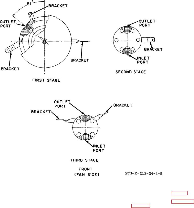
Figure 4-9. First-, second-, and third-stage port and bracket orientation.
(2) Remove protecting cage (para 3-7).
4-28.
Second Stage
(3) Remove  fan  group  (para  4-54)
a
Preliminary.
Remove screw (3, fig. 4-10) and lock12).washer (4) at
bracket (5).
(1) Remove canvas group (TM 3-1040-
263-12).
4-16


Privacy Statement
Press Release
Contact

© Copyright Integrated Publishing, Inc.. All Rights Reserved.