
TM 3-1040-263-34
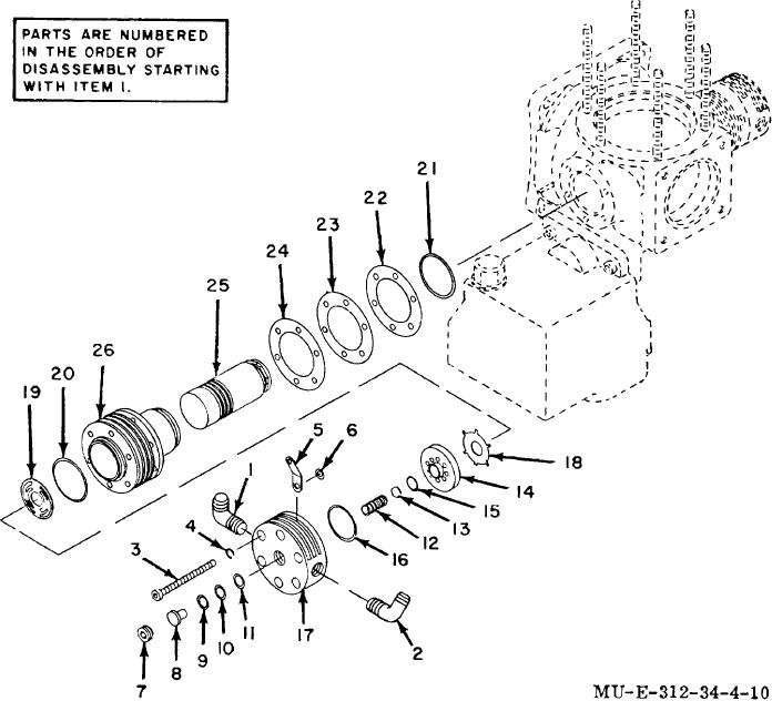
1
Elbow
10
Spacer
19
Inlet spring
2
Elbow
11
Spacer
20
Head gasket
3
Screw
12
Discharge spring
21
Preformed packing
4
Lockwasher
13
Discharge valve
22
Shim
5
Bracket
14
Valve plate
23
Shim
6
Washer
15
Plate seal
24
Shim
7
Lockscrew
16
Plate gasket
25
Plunger
8
Valve stop
17
Head
26
Cylinder
9
Spacer
18
Intake valve
Figure 4-10. Second-stage section-exploded view.
(19) Position shims (22 through 24) and
(15) Disassemble parts used to determine
preformed packing (21) onto the cylinder (26).
second stage head clearance.
(20) Position the cylinder (26) into the crankcase
(16)
Lubricate all parts with compressor oil prior to
second-stage opening, a lining the mounting holes.
assembly.
(21) Repeat steps (12) through (14) above to
(17) Position compression ring gaps 1200 apart
with bevel of rings toward top of plunger (25).
insure correct head clearance.
(22) Position head gasket (20) and inlet
(18) Slide plunger (25) into cylinder (26).
4-18