
TM 3-1040-263-34
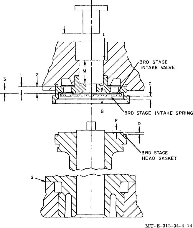
Figure 4-14. Third-stage valve travel and head clearance.
(16) Position shims (22, 23, and 24) and
(19) Position inlet spring (19), with legs of
inlet
preformed packing (21) onto the third-stage cylinder and
spring pointing down, onto third-stage cylinder
and
plunger assembly (25).
plunger assembly (25).
(17) Position cylinder and plunger assembly into
(20) Position inlet valve (18) on bow of
inlet
crankcase third-stage opening; aline holes.
spring (19). (21) Position third-stage head gasket
(20)
(18) Recheck head clearance ((13) above).
4-23