
TM 3-1040-263-34
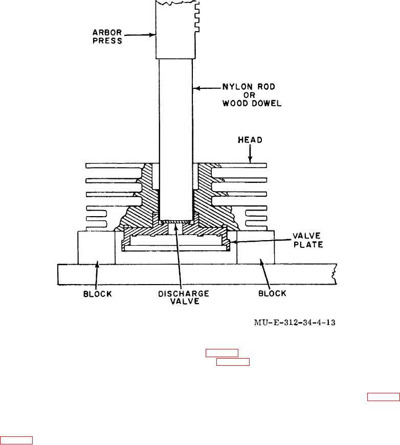
Figure 4-13. Third-stage valve plate removal.
4-12) to obtain discharge valve travel between 0.017 and
fig. 4-12) on the cylinder. Then, determine measurement
0.021 inch.
(11) Determine measurement B (fig.
(8) Position outlet spring (12) on outlet
(12) Obtain result of B minus D and E dimension
valve (13). Position shims (9, 10, and 11) selected in (7)
F from result to obtain available clearance.
above and valve stop (8) into third-stage head (17).
(13) Add all or part of shims (22, 23, fig. 4-12)
Secure in place using screwlock (7). Torque screwlock
to obtain required head clear between 0.035 and 0.041
(7) to 12.5 pound-feet.
inch.
(9) Position third-stage cylinder and
(14) Disassemble parts used to d third-stage
plunger assembly (25) on crankcase. Rotate crankshaft
head clearance.
(13, fig. 4-16) until the third-stage plunger is at top dead
(15) Lubricate all parts with compound prior to
center while seated on the keystone assembly plunger
assembly.
interface surface. Determine measurement F (fig. 4-
14).
(10) Position the third-stage head gasket (20,
4-22