
TM 3-1040-263-34
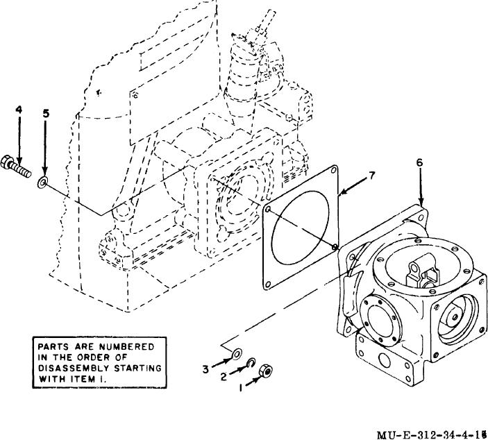
1
Nut
3
Washer
6
Crankcase assembly
2
Lockwasher
4
Bolt
7
Gasket
5
Washer
Figure 4-15. Crankcase Assembly removal.
race inside of crankcase. With pins properly positioned,
(8), and counterweights (9) from the crankshaft (13).
press the pins to remove the rear bearing (5) from the
f.
Using a 5/32-inch diameter by 3-inch long
crankshaft (13). Remove crankcase from arbor press.
steel drift pin, press the keystone roll pins (10) from the
With rear bearing (5) removed from
d.
keystone assembly (14), using an arbor press. Then,
crankshaft (13), move crankshaft with assembled
remove the keystone wedge (11) and fork (12) from the
keystone assembly to rear of crankcase (17), and
crankshaft (13).
remove the crankshaft from the crankcase through the
first stage opening.
4-34.
Cleaning and Inspection
e. Remove the lockwire (6), and unscrew the
four screws (7); remove screws and lockwashers
a. Use a soft-bristle brush to clean apertures,
slots, and holes.
Pay particular attention to the
4-25