
TM 3-1040-263-34
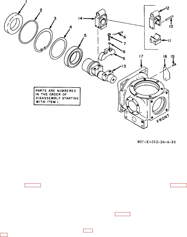
1
Seal
7
Screw
13
Crankshaft
2
Preformed packing
8
Lockwasher
14
Keystone assembly
3
Retaining ring
9
Counterweight
15
Drive screw
4
Spacer
10
Roll pin
16
Nameplate
5
Bearing
11
Wedge
17
Figure 4-16. Keystone and crankshaft exploded view.
crankcase (17, fig. 4-16) and crankshaft (13) passages.
g. Inspect keystone fork (12, fig. 4-16) and
wedge (11) for permanent marks indicating that
components are matched parts. Keep matched parts
b. Clean all metallic parts except the rear
together.
bearing (5) in drycleaning solvent.
h. Reassemble the keystone assembly (14),
c. Apply compressor lubricating oil to cleaned
and measure the diameter tolerances of the keystone
parts to prevent rusting.
d. Inspect all parts for wear or damage.
bores (para 1-4c).
e. Inspect all threads for damage.
4-35. Reassembly
NOTE
f.
Check crankshaft diameter tolerance (para
Fork and wedge are matched parts and are absolutely
not interchangeable with similar parts.
4-26