TM 5-4310-227-15
installation (Model OEG-458-ENG-3)
Section X.
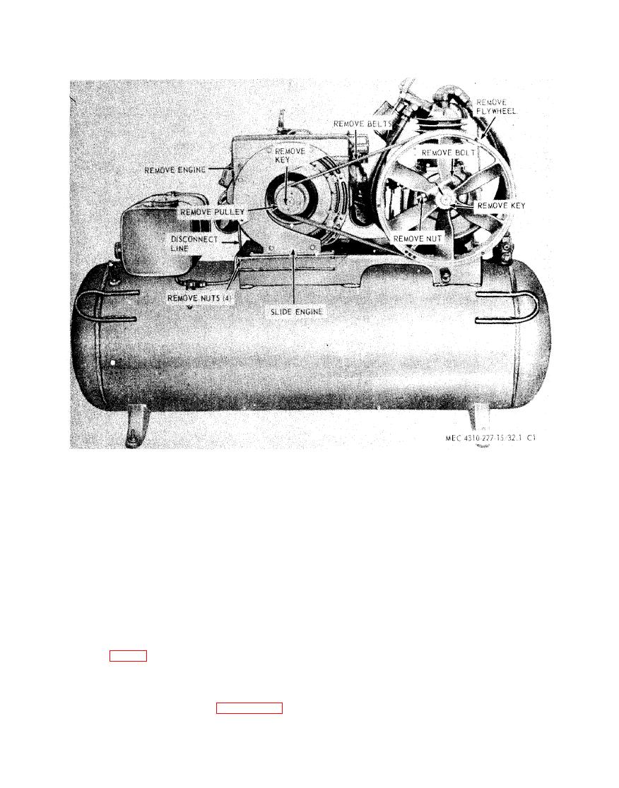
ENGINE AND COMPRESSOR REMOVAL
AND INSTALLATION
(1) Remove the screws (8) and remove
3-60. General
top enclosure (22).
(2) Remove door enclosures (9 and 23).
units may be relplaced as individual and com-
plete units. They are bolted to the mounting
(3) Remove fastener (38) and then re-
base and connected to each other by a belt set.
move guards (40 and 45).
b. The entire engine and compressor assem-
(4) Remove the screws (8) and remove
b l y on models BMW-452-ENG and BMW-
dust end enclosure (7) and louver
452-ENG-1 may be removed by removing the
end enclosure (24).
nuts (1, fig. 3-9) and bolts (2) from the base
(3).
(5) Remove nuts (34), washers (33), an-
c. On models BMW-452-ENG and BMW-
chor plates. (32), anchor bolts (31),
452-ENG-1 the entire shroud assembly must
and then remove base channel assem-
be removed first as shown in figure 3-24 and
bly (1).
as follows:


