necessary to insure proper operation of the air
compressor.
Refer to figure 19 for removal and installation
(1) Disconnect batteries before doing any
of the lights and mounting parts.
work on instrument panel.
(2) Disconnect air and oil lines and elec-
trical leads from any portion of in-
a. On-Engine Testing. Defects in the gener-
strument panel to be worked on.
ator or the regulator are indicated on the am-
Warning: Release all air pressure
meter by a continuous high-charging rate when
from the air compressor prior to per-
the battery is fully charged, or by a low-or-no-
forming any maintenance on the unit.
charging rate when the battery is low.
b. Disassembly and Removal.
(1) Refer to figure 21 and remove items
(1) When a high-charging rate is indi-
1, 2, 3, 4, 5, 6, 7, 8, 9, 10, 11, and 28.
cated, run the engine at operating
(2) Remove nuts (30), washers (31), and
speed and disconnect the field terminal
screws (32). Remove panel (33) from
lead from the regulator. If the output
enclosure.
remains high, the trouble is in the
generator. Replace a defective gen-
c. Cleaning and Inspection.
(1) Clean all parts, except electrical com-
erator (para 64). If the output drops
ponents, in an approved cleaning sol-
off, the trouble is in the regulator.
vent; dry thoroughly.
Adjust the regulator or replace a de-
(2) Clean electrical leads and terminals
fective unit.
with a cloth dampened with an ap-
(2) When a low-or-no-charging rate is in-
dicated, inspect for loose connections,
frayed or damaged wires, or a defec-
tive battery. If none of these condi-
tions exists, operate the engine at a
medium speed and momentarily
ground the field terminal of the regu-
lator. No increase in the output indi-
cates a defect in the generator. Re-
place a defective generator (para 64).
An increase indicates the regulator is
faulty. Replace a defective regulator.
(3) Momentarily connect a jumper lead be-
tween the battery terminal and the
generator terminal, to polarize the
generator.
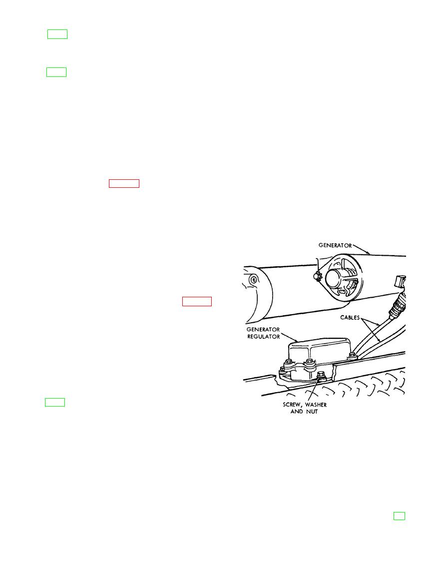
b. Removal and Installation. Refer to figure
20 and remove or install the generator regu-
lator.
a. General. All controls and instruments nec-
essary for operation of the air compressor are
TO REMOVE GENERATOR REGULATOR:
mounted on the instrument panel located within
STEP 1. DISCONNECT THE TWO CABLES FROM
the enclosure. Controls and instruments must
GENERATOR REGULATOR.
be replaced when they become inoperative or
STEP 2. REMOVE NUTS, LOCKWASHERS AND
show signs of incorrect readings during normal
SCREWS.
operation. Care should be taken in handling
STEP 3. REMOVE GENERATOR REGULATOR.
controls and instruments, since they are sensi-
MEC 4310-247-15/20
tive and are adjusted accurately. Replace con-
trols accurately, because their adjust-merits are
AGO 8166A


