ing or pressing the gear on the shaft
having over .005 inch clearance be-
tween shaft and arm. Inspect the
does not cause the shaft to bump the
rocker arm brackets for cracks or
expansion plug at the rear end, forc-
ing it out of position and causing an
other damage.
(7) Inspect push rods for bends or twists
oil leak.
and examine the ball and cup ends for
Install any tappets (16) which were
(2)
excessive wear. Replace rods that are
removed for examination or replace-
faulty or excessively worn.
ment. Tappets can be removed from
(8) Check the clearance of the camshaft
the top of the block without pulling
journal in the bearing hole or bushing.
the camshaft, by means of a mag-
If the clearance equals or exceeds the
n e t i z e d rod.
wear limits given in paragraph 94,
(3)
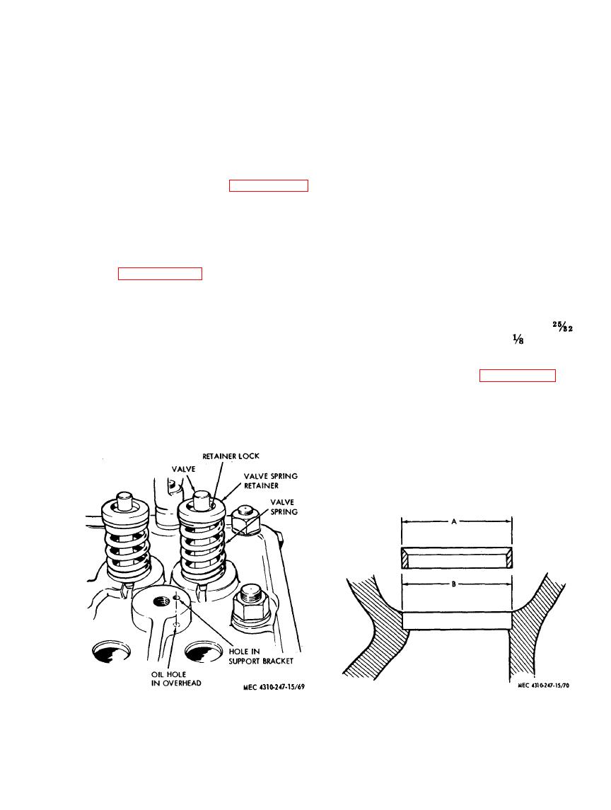
Refer to figure 69. First coat the valve
check the diameter of the camshaft
stems with a light film of engine oil,
journals. If the wear is excessive, the
then reassemble the valves (24, fig.
camshaft must be replaced.
66) and springs (20) in the head with
(9) Check the outside diameter of all tap-
the retainers (19) and retainer locks
pets (16) with micrometer and re-
(18). The close-wound coils of the
place if excessively worn. Refer to
valve spring should contact the cylin-
der head.
scores or damage to contact face. Two
(4)
Replace worn guides (22) by pressing
or three small pits is acceptable; re-
in new guides from the combustion
place if excessively pitted.
side to the correct depth below the cyl-
(10) Examine the camshaft thrust plate
inder head contact surface (2
(32) for scoring and wear. Replace
inch for intake guides, 3
inch for
if unsatisfactory.
e x h a u s t guides).
(5)
Ream new valve stem guides to sise if
c. Reassembly and Installation. Reassemble
necessary. Refer to paragraph 94.
and install the rocker arm and camshaft parts
Caution: Ferrox coated guides are
of the engine as shown in figure 66.
now used on some models. These are
(1) Assemble the cam gear (29) to the
pre-reamed and they do not require
camshaft (35) by holding the cam-
further reaming after installation.
shaft forward so that the act of driv-
(6)
When replacing valve seat inserts
with new inserts, clean and counter-
bore for .010 inch larger insert. Limits
are 1.6888/1.687 inch for inside diam-
eter of counterbore (B), and 1.692/
Figure 69. Valve reassembly.
Figure 70. Valve seat insert.
AGO 8166A
91


