to the torque specified. Use lockwires, cotter
pins, or lockwashers as required, to prevent
nuts and screws from becoming loose.
(1) Assemble the pistons (45) on the con-
necting rods (36) at room tempera-
ture (approx 75 F.). Tap the pins
(44) into place through the rod bush-
ing (41). The piston pin hole in the
connecting rod must be parallel to and
in plane with the large bore in the
bearing end of the rod. The snap rings
(43) must be firmly seated in the
grooves.
(2) Install piston rings (46, 47, 48, and
49). Grip the connecting rod (36) in
a vise with leadlined jaws to hold the
piston (45) firmly, and roll each ring
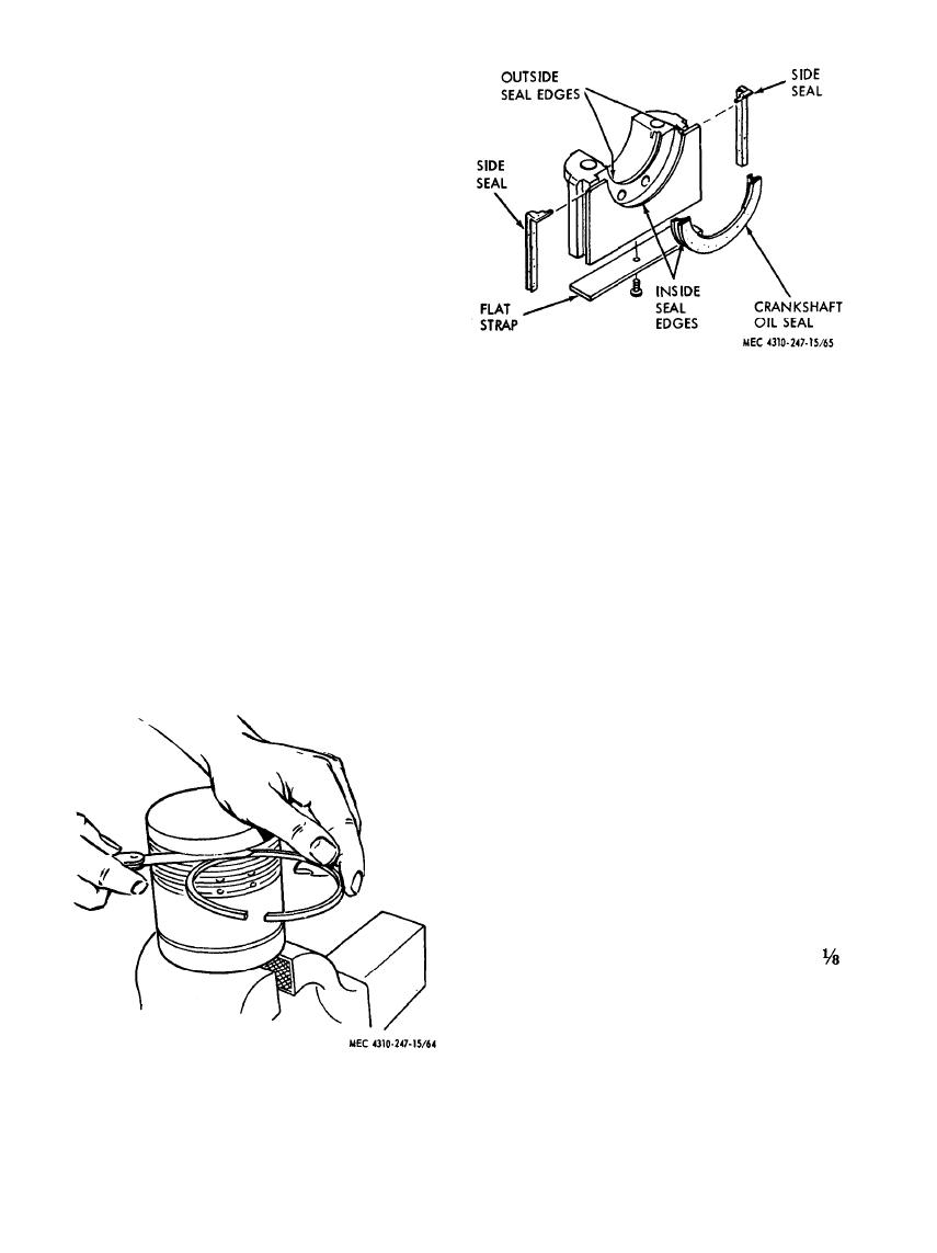
Figure 65. Filler block and seal reassembly.
in its groove to make sure there are no
seal lip to make sure sealing surface
burrs or other material to impede the
is clean, smooth, and free from nicks.
free action of the ring in the groove.
Apply a thin coating of seal lubricant
Start with the lowest ring (49).
to lip surface before installing, and
Caution: Do not expand rings more
break edge slightly on both the cap
than necessary to fit over piston. Ex-
and the block, to prevent cutting the
cessive expansion of a ring may cause
seal during installation. Coat outside
distortion which can not be detected
seal edge (contacting the groove) with
by visual inspection. Tapered piston
cement.
rings must be installed with top side
Note. This oil seal can be installed without
up.
removing the crankshaft. In this case, use
(3) Refer to figure 65 and install crank-
only light grease in the seal groove in the
shaft oil seals on engine block and
cylinder block when sliding the seal in place.
Apply pressure to the seal so that it will hug
bearing cap (22, fig. 57). Check oil
the crankshaft. This also helps to move it
into place.
(4) Slide the side seals (fig. 65) into the
filler grooves without oil. Then coat
the outside edge lightly with an oily
finger to help slide in the block with-
out stretching.
(5) Apply a light coat of cement to the tab
end side seal surfaces that contact
both the block and filler block. Allow
it to become tacky before assembling.
Caution: Do not use too much
cement. Make sure no cement gets on
lip of seal.
(6) Bolt a flat strap (fig. 65) (approx
by 1 by 6 in.) to bearing cap, using
the same hole that was used for puller.
This strap will hold the side seals in
place during assembly to block. After
assembly, remove strap. The side
slabs should not project more than
Figure
64.
Ring
groove
clearance.
AGO 8166A
88


