TM 5-4310-276-14
(3) If necessary to remove switch, remove hex
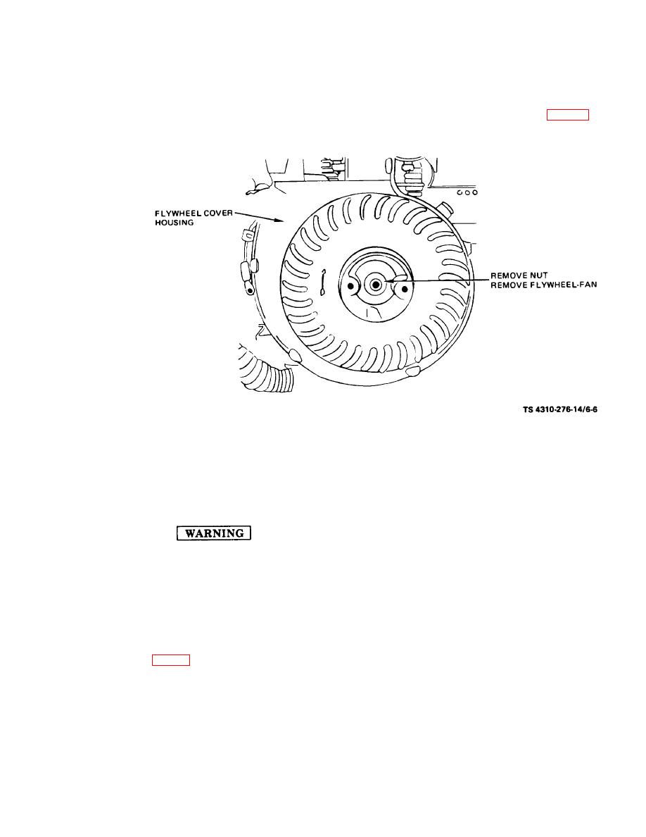
(2) Remove seven screws and remove flywheel
nut on switch and push switch through hole in cov-
fan cover. Lay cover back with ignition leads at-
er.
tached.
(3) Inspect flywheel-fan for cracks, breaks, ev-
(5) Use a suitable puller and remove flywheel-
idence of rubbing, bent or broken guide vanes and
fan. Remove key from shaft.
b. Cleaning and Inspection.
distortion.
(4) Inspect hub and keyway for evidence of
misalignment, damage or excessive wear. Inspect
bolt holes for stripped or damaged threads.
(5) Repair or replace any damaged or de-
Drycleaning solvent, P-D-680, used to
fective part.
clean parts is potentially dangerous to
c. Installation.
personnel and property. Avoid re-
(1) Place key in keyway of shaft.
peated and prolonged skin contact.
(2) Use a plastic hammer or a wooden block
Do not use near open flame or exces-
and tap the flywheel fan onto the shaft.
sive heat.
240-300 inch-pounds.
(1) Clean flywheel-fan with drycleaning sol-
(4) Install starter flange.
vent, item 5, App. D.
(5) If ignition switch was removed, push it
(2) Inspect starter flange and mounting bolts
through hole in fan cover and install hex nut.
for cracks, breaks and elongated mounting holes.
(6) Install flywheel fan cover and fasten with
Inspect mounting bolts for stripped or damaged
seven screws.
threads, damaged heads and a serviceable lock-
washer installed.
6-7


