TM 5-4310-276-14
areas, broken mounting flanges, elongated mount-
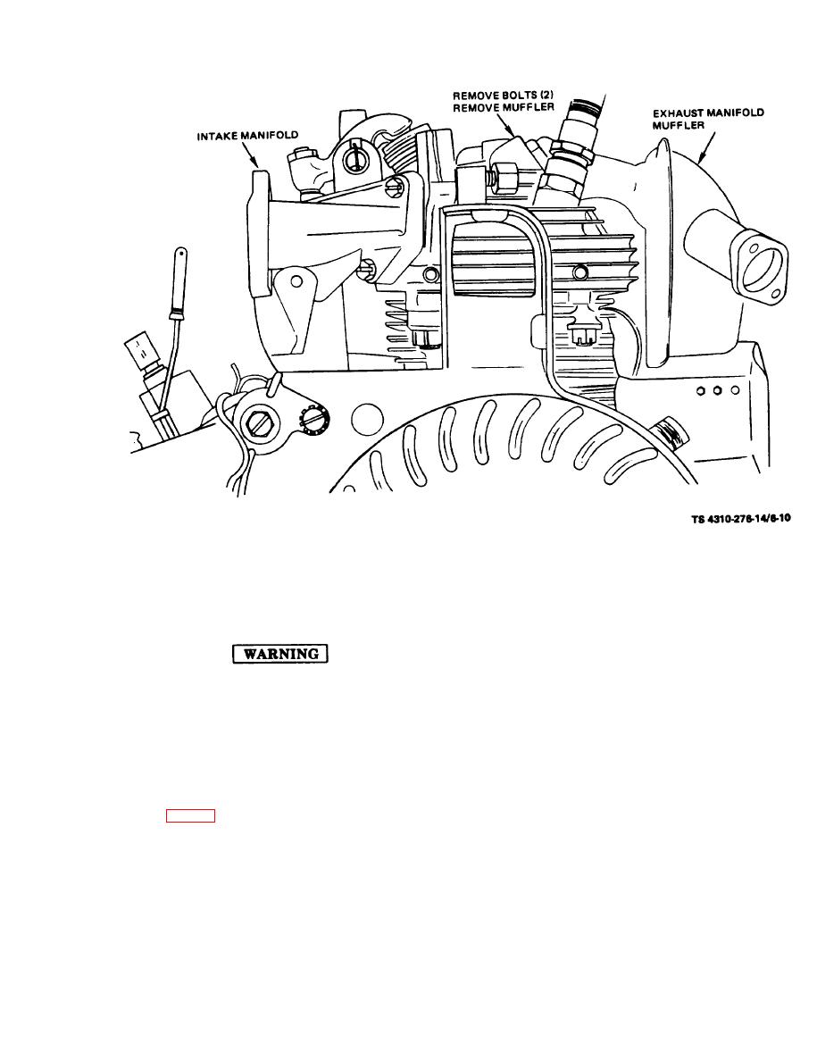
(a) Remove two bolts.
ing holes, dents, scratched or gouged mounting sur-
b. Cleaning, Inspection and Repair.
faces, cracks and defective weldments.
(3) Repair or replace any damaged or de-
fective part.
c. Installation.
(1) Models 1A08-2 and 1A08-3.
Drycleaning solvent, P-D-680, used to
clean parts is potentially dangerous to
attach with two screws.
personnel and property. Avoid re-
peated and prolonged skin contact.
inch-pounds.
Do not use near open flame or exces-
(2) Model 1A08-1.
sive heat.
(a) Install exhaust manifold with two
screws.
(1) Clean all parts with drycleaning solvent,
(b) Install duct with four screws.
item 5, App. D.
inch-pounds.
(3) Install side cylinder head covers and
attach with screws.
6-11


