Table 1. Tabulated Data (For Model 60CAW20HM-1)
Bore and Stroke . . . . . . . . . . . . . . . . . . . . . . . . . . . . 2-5/8 x 2 first stage (2 cyl); 1-3/4 x 2 second stage
CU. FT/REV . . . . . . . . . . . . . . . . . . . . . . . . . . . . . . . . . . . . . . . . . . . . . . . . . . . . . . . . . . . 0.01252
Air Receiver Working Pressure . . . . . . . . . . . . . . . . . . . . . . . . . . . . . . . . . 200 psi at -25° to+450°F
Displacement . . . . . . . . . . . . . . . . . . . . . . . . . . . . . . . . . . . . . . . . . . . . . . . . . . . . . . . .9.3 CFM
Delivery . .. . . . . . . . . . . . . . . . . . . . . . . . . . . . . . . . . . . . . . . . . . . . . . . . . . . . . . . . .6.5 CFM
Crankcase capacity . . . . . . . . . . . . . . . . . . . . . . . . . . . . . . . . . . . . . . . . . . . . . . . . . . . . . . .
1 pint
Shipping weight . . . . . . . . . . . . . . . . . . . . . . . . . . . . . . . . . . . . . . . . . . . . . . . . . . . . . . . . . 282 lbs
Overall Dimensions . . . . . . . . . . . . . . . . . . . . . . . . . . . . . . . . . . . . . . . . . . . . . . . . . 39" x 22" x 52"
Power Requirements . . . . . . . . . . . . . . . . . . . . . . . . . . . . . .
208-220 or 416-440 volts, 60 cps, 3 phase
2. INSTALLATION
3. LOCATION AND MOUNTING
Installation should be accomplished on a solid,
level base, preferably concrete, with at least 14
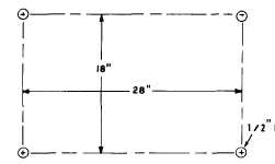
inches clearance at the belt guard assembly. Figure
2 shows drilling dimensions for bolting or lagging
down through bolt holes in the base feet. Shims should
be used where the base is uneven. Base feet should
never be pulled down to the base as this results in
abnormal vibration.
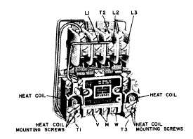
4. HEAT COIL SELECTION (See figure 3)
The magnetic motor starter contains two pairs of
overload heat coils.
One pair is for 208-220 volt
service and the other pair is for 416-440 volt service.
Install the correct heat coils on the two thermal over-
loads (5 & 8, fig. 6). Secure the remaining pair
of heat coils inside the magnetic motor starter box
for possible future use.
5. ELECTRICAL CONNECTIONS
Ascertain that available electrical service is 208-
220 or 416-440 volts, 60 cps, 3 phase. Shut off elec-
trical service and make wiring connections shown in
figure 4.
Be sure that V, M, and W terminal wiring
corresponds to available voltage.
CAUTION
Figure 2. Drilling Dimensions for Mounting
Figure 3. Magnetic Motor Starter
Do not allow electrical service to be turned on until crankcase has been filled with oil.
Figure 4. Electrical Wiring
2


