28. VALVE ASSEMBLIES. (See fig. 10) When any
valve assembly is removed, always install a new
valve gasket. Be sure to replace a valve assembly in
its original position.
29. CRANKCASE HAND HOLE PLATE. When hand
hole plate (See fig.9) is removed for any reason,
always install a new hand hole gasket (22).
30. CRANKSHAFT BEARING ASSEMBLIES. (See
fig. 9) The bearing assemblies are pressed onto
the crankshaft up against a shoulder. Be sure to
press bearing cone and roller and bearing cup until
positive stop is reached.
(See fig.
9)
3 1 . P I S T O N C O N N E C T I N G R O D S
When installing a new piston connecting rod, be sure
that both parts of the new rod are used. Both parts of
the old rod must be discarded.
32. PISTON RINGS. (See fig. 9) Piston rings
are received in sets and upper and lower rings are
identified in the sets.
33. TEST PROCEDURE
Table 3 indicates the minimum performance
standards that the equipment must meet. To make the
test, perform the following steps.
a.
b.
c.
d.
e.
f.
Place toggle switch (2,fig. 6) to off (down)
position.
Remove air hose assembly (fig. 1) from
g l o b e v a l v e a s s e m b l y ( 1 5 , f i g . 8 ).
Open globe valve assembly (CCW) until pressure
gage
indicates 0 psi, then close valve as-
sembly.
Reconnect air hose assembly and open globe
valve assembly.
Place toggle switch to on (up) position and
check pumping time according to table 3. If
cut-out pressure is incorrect, adjust accord-
ing to paragraph 34.
Operate inflator gage assembly to lower air
pressure until compressor starts.
If cut-in
pressure is incorrect, adjust according to
paragraph 34.
Table 3. Minimum Pumping Time Requirements
PRESSURE
PUMPING TIME
0 to 100 psi
12 minutes
0 to 125 psi
15 minutes
0 to 150 psi
18 minutes
0 to 175 psi
21 minutes
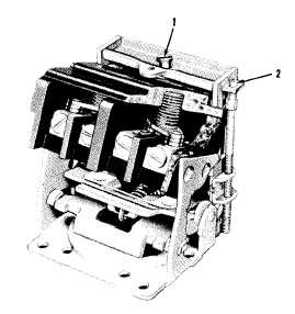
34. ADJUSTMENT
a. To raise cut-in and cut-out pressure, turn
screw (1, figure 5) on pressure switch assem-
bly clockwise.
CAUTION
Do not turn screw (2) further that it
will turn easily.
1. PRESSURE ADJUSTMENT SCREW
2. DIFFERENTIAL ADJUSTMENT SCREW
Figure 5. Pressure Switch Assembly Adjustments
b. To lower differential (difference between cut-
in and cut-out pressure), turn screw (2) coun-
terclockwise.
c. To increase differential and maintain same
cut-out pressure, simultaneously turn screw
(2) clockwise and turn screw (1) counterclock-
wise.
NOTE
If differential is increased by turning
only screw (2) clockwise, the cut-in
pressure changes only slightly and the
cut-out pressure rises.
35. TROUBLESHOOTING
Table 4 lists troubles that may occur during in-
stallation, operation and test. One or more remedial
steps are indicated for each of the troubles.
5
307-967 O - 68 - 2