
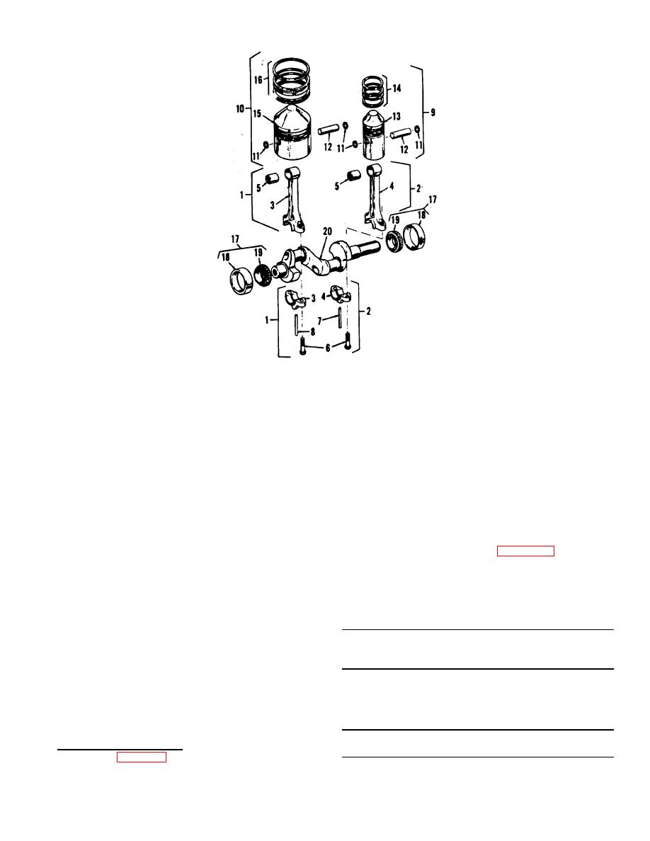
1. Kit connecting rod assembly L.P.
11.
Ring, piston pin retaining
2. Kit connecting rod assembly H.P.
12.
Pin, piston
3. Rod, connecting w/bolt L.P.
13.
Piston, high pressure
4. Rod, connecting w/bolt H.P.
14.
Ring set, H.P. piston
5. Bearing, piston pin
15.
Piston, low pressure
6. Bolt, connecting rod
16.
Ring set, L.P. piston
7. Dipper, oil H.P.
17.
Assembly, main bearing
8. Dipper, oil L.P.
18.
Cup, bearing,
9. Kit, piston assembly H.P.
19.
Cone & roller, bearing
10. Kit, piston assembly L.P.
20.
Crankshaft
Figure 18. Crankshaft, piston and connecting rod assemblies, exploded view.
to slide freely over the piston to the proper
b. Remove the hand hole plate and flywheel.
position. Starting with the bottom ring,
c. Remove bearing caps (figure 18) and push
install piston rings in their proper grooves
connecting rods and pistons up to the top of the
Stagger ring gaps so that they are not lined
cylinder bore. Remove the cap screws that
up.
secure unloader housing to crankcase.
3.
Lubricate each piston and connecting rod
d. Drive the crankshaft, bearings, and unloader
assembly with a light cost of engine oil
housing from the crankcase.
before installing in cylinder block.
Compress the piston rings carefully when
CAUTION: Before driving the crankshaft from the crank-
installing in cylinder.
case, be sure the connecting rod journals are in an
4.
When installing cylinder block to crankcase
upright position.
always use new flange gasket and torque
nuts to 45 ft.-lbs. torque.
e. Using suitable puller remove the unloader
5.
Torque connecting rod nuts to 25 ft.-lbs.
housing and bearing from the shaft.
torque.
f. Remove the oil seal from the crankcase.
B. CRANKSHAFT AND CRANKCASE
NOTE: Do not remove the oil level gage from the
1. Removal and Disassembly.
crankcase unless the gage is leaking or defective.
a. Refer to figure 7 and remove the unloader
assembly.
19
