TM 5-4310-354-14
REMOVAL
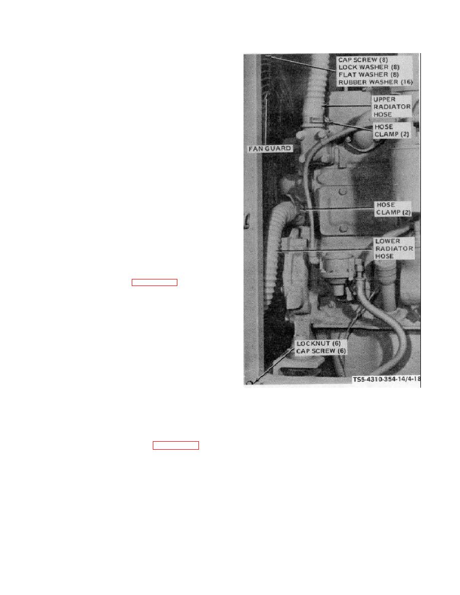
STEP 1.
LOOSEN HOSE CLAMPS, DISCONNECT,
AND REMOVE UPPER RADIATOR HOSE.
LOOSEN HOSE CLAMPS, DISCONNECT,
AND REMOVE LOWER RADIATOR HOSE.
STEP 2.
REMOVE
CAP
SCREWS,
LOCK
WASHERS, SPECIAL FLAT WASHERS,
RUBBER WASHERS, AND FAN GUARD.
STEP 3.
ATTACH A SUITABLE LIFTING DEVICE,
SUCH AS A CHAIN HOIST, TO THE
RADIATOR
AND
OIL
COOLER
ASSEMBLY.
STEP 4.
REMOVE LOCKNUTS AND CAP SCREWS
THAT ATTACH RADIATOR AND OIL
COOLER ASSEMBLY TO THE FRAME.
USING THE LIFTING DEVICE, LIFT THE
ASSEMBLY OFF THE UNIT AND PLACE
IN DISASSEMBLY WORK AREA.
INSTALLATION
STEP 1.
AFTER ASSEMBLY OF RADIATOR AND
OIL COOLER (FIG 4-19), USE A
SUITABLE LIFTING DEVICE AND PLACE
THE ASSEMBLY IN POSITION ON UNIT
FRAME. ATTACH THE ASSEMBLY WITH
CAP
SCREWS
AND
LOCKNUTS.
REMOVE THE LIFTING DEVICE.
STEP 2.
ATTACH FAN GUARD TO SHROUD WITH
RUBBER WASHERS, SPECIAL FLAT
WASHERS, LOCK WASHERS, AND CAP
SCREWS.
TS 5-4310-354-14/4-18
STEP 3.
INSTALL LOWER RADIATOR HOSE AND
SECURE WITH HOSE CLAMPS. INSTALL
UPPER RADIATOR HOSE AND SECURE
WITH HOSE CLAMPS.
Figure 4-18. Radiator and oil cooler group, removal and installation.
b. Disassembly.
Refer to figure 4-19 and
(3) Remove four screws (10) and bottom fan
disassemble the radiator and oil cooler assembly in the
guard (11). Remove eight lock nuts (12),
sequence order of index numbers in the figure as
eight screws (13), and fan shroud (14).
follows:
(4) Attach a suitable lifting device, such as a
(1) Remove the two tubing elbows (1), two
chain hoist, to the radiator assembly (17),
couplings (2), and two nipples (3) from
remove the four cap screws (15), four lock
bottom of oil cooler assembly (25).
washers (16), and remove the radiator
assembly (17) away from end panel (28)
(2) Unscrew and remove drain cock (4),
pulling nipple (18) out of grommet (19).
coupling (5), nipple (6), and elbow (7).
Remove nipple (18) from radiator
Remove fourteen screws (8) and radiator
assembly (17) and remove the grommet
guard (9).
(19).
4-38


