TM 5-4310-354-14
minimum pressure valve piston should lift
c. Installation.
off its seat at approximately 70 psi
allowing air to pass through the valve.
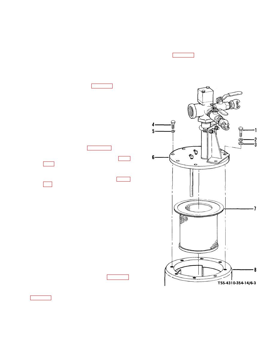
(1) Install the oil separator element in the
reverse numerical sequence shown in
(3) Close the control valve reducing the test
figure 6-3 as follows:
pressure to less than 70 psi.
Spring
pressure on the piston should seat the
(a) Install separator element (7) in
piston stopping flow of test air through the
separator tank (8) with flange of
minimum pressure valve assembly.
element resting on top of tank.
Should the assembly not function in this
manner, the spring (4, figure 6-2) and o-
ring (6) shall be replaced.
(4) Close the test air control valve and
remove the minimum pressure valve
assembly from the test setup.
6-4.
Oil Separator Element.
a. Removal.
(1) Disconnect air lines necessary for removal
of oil separator cover (figure 4-22).
(2) Remove the hose reel assembly (para
(3) Remove oil separator cover and element
in the numerical sequence shown in figure
6-3 as follows:
(a) Remove two cap screws (1), two
lock washers (2), and two flat
washers (3) located at support
bracket.
(b) Remove the remaining six cap
screws (4) and six lock washers (5)
attaching cover assembly (6) to
separator tank (8).
(c) Lift cover assembly (6) straight up
so that separator element (7) is not
damaged by oil pipe attached to the
underside of the cover assembly (6).
Lift out the separator element (7).
for holes, varnishing condition, distortion, or any other
TS5-4310-354-14/6-3
defect.
Figure 6-3. Oil separator element, removal and
KEY to figure 6-3:
installation.
1. Cap screw (2)
5.
Lock washer (6)
2. Lock washer (2)
6.
Cover assembly
3. Flat washer (2)
7.
Separator element
4. Cap screw (6)
8.
Separator tank
6-5


