TM 5-4310-354-14
1.
Cap screw
5.
O-ring
2.
Cap screw (5)
6.
Rotor blade (8)
3.
Seal washer (6)
7.
Rotor
4.
Intake housing and
8.
Stator
end cover assembly
TS5-4310-354-14/6-10
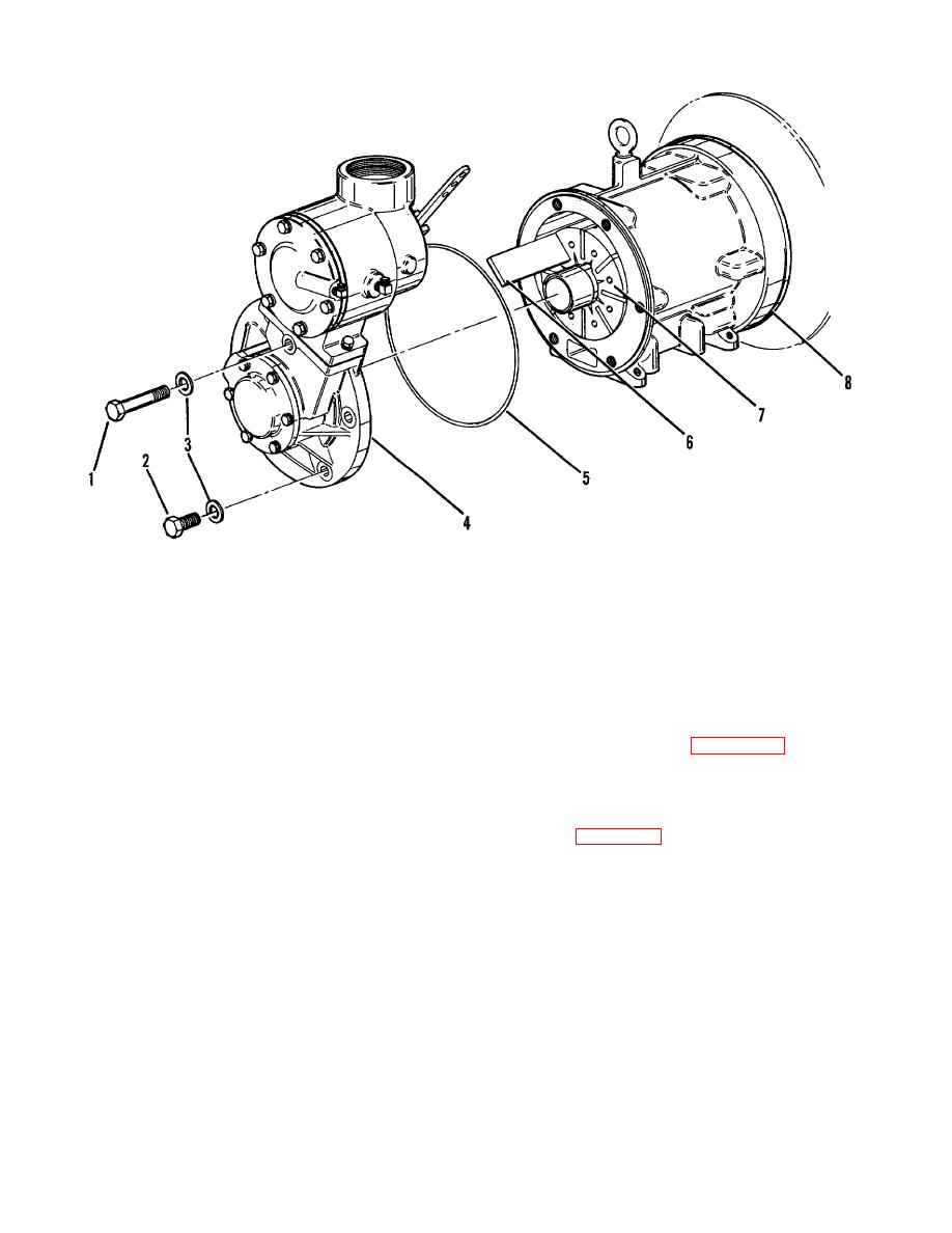
Figure 6-10. Compressor non-drive end, disassembly, blade inspection, and reassembly
(a) Remove one cap screw (1), five cap
instrument panel momentarily to
screws (2), and six seal washers
rotate engine and compressor rotor
(3). Tap intake housing and cover
to bring blades to a position where
assembly (4) with a soft mallet while
they can be removed.
pulling away from stator (8).
Remove the housing and cover
b. Inspection.
Inspect blades for evidence of
assembly (4). Remove o-ring (5).
excessive wear.
See figure 6-11.
Blades are
excessively worn when 25 percent of covering, per side,
(b) Remove the eight rotor blades (6)
has been worn off, and shiny metal is exposed. Blades
from rotor (7) slots using a small
worn on one side only can be turned around and reused.
wire with one end bent to form a
Replace blades that have been worn /'h-inch (1.59 mm)
hook. To remove the blades which
in height (figure 6-11). Replace blades worn on both
are on the bottom of the rotor, press
sides, chipped, or damaged in any other way.
the start pushbutton on the
6-20


