TM 5-4310-354-14
Section VI. FUEL TANK
6-15. General. The fuel tank is located on the unit
6-16. Fuel Tank.
frame mounted below the radiator and oil cooler group.
The tank has a capacity of 19 gallons (71.9 liters) and
a. Removal.
incorporates an electrically operated fuel level sending
unit. The sending unit is of the float type which sends an
(1) Disconnect the two wire assemblies from
electrical impulse to the fuel level gauge located on the
fuel level sending unit.
instrument panel where the level of fuel remaining in the
(2) Disconnect the fuel pickup and return
tank is read. Fuel is drawn from the tank by the engine
hose assemblies from the tank.
transfer pump and then flows to the fuel injection pump.
The fuel injection pump meters the correct amount of
(3) Remove fuel tank drain plug and drain fuel
fuel required for each cylinder and pumps this fuel to
from tank. Install drain plug.
each fuel injection nozzle in the proper firing order.
More fuel than is necessary for engine operation passes
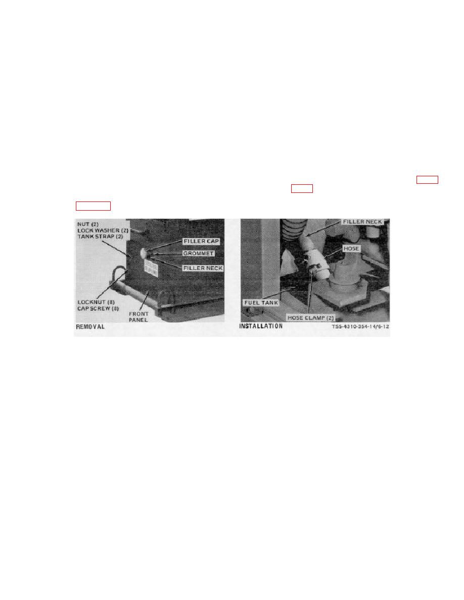
(4) Remove the fuel tank as shown in figure
through the fuel injection pump for lubrication and
cooling of the pump. This excess fuel flows back to the
fuel tank. See figure 5-3.
TS5-4310-354-14/6-12
STEP 1.
REMOVE THE FUEL TANK FILLER CAP.
STEP 1.
AS NECESSARY, USE A SUITABLE
LOOSEN HOSE CLAMPS AND REMOVE
GLUE TO ATTACH WEBBING TO FUEL
FUEL FILLER NECK AND CONNECTING
TANK STRAPS. INSTALL FUEL TANK
HOSE WITH CLAMPS.
STRAPS AND ATTACH TO FRAME WITH
CAP SCREWS, LOCK WASHERS, AND
NUTS.
STEP 2.
REMOVE NUTS AND LOCK WASHERS
STEP 2.
INSTALL FUEL TANK IN POSITION.
THAT SECURE FUEL TANK STRAPS TO
INSTALL FRONT PANEL AND ATTACH
FRAME FRONT PANEL.
TO FRAME WITH CAP SCREWS AND
LOCK NUTS.
STEP 3.
REMOVE LOCKNUTS AND CAP SCREWS
STEP 3.
INSTALL FUEL TANK FILLER NECK
THAT ATTACH FRONT PANEL TO
THROUGH GROMMET IN FRONT PANEL
FRAME. REMOVE THE FRONT PANEL.
AND INSTALL HOSE CONNECTION ON
TANK AND FILLER NECK. TIGHTEN THE
HOSE CLAMPS.
STEP 4.
REMOVE THE FUEL TANK.
WHEN
STEP 4.
INSTALL LOCK WASHERS AND NUTS
NECESSARY, REMOVE NUTS, LOCK
ON STUD ENDS OF FUEL TANK STRAPS
WASHERS, CAP SCREWS, AND FUEL
AND SECURE TANK FIRMLY TO FRAME
TANK STRAPS WITH WEBBING
BY TIGHTENING THE NUTS ON TANK
STRAPS.
INSTALL THE FUEL TANK
FILLER CAP.
Figure 6-12. Fuel tank, removal and installation.
6-23


