TM 5-4310-354-14
(3) Place rotor assembly (8) in a vise and
tighten only enough to remove shaft nut
(2). Remove the nut (2), lock washer (3),
pulley (4), fan (5), and outside collar (6)
from rotor (8) shaft.
Separate rotor
assembly (8) from drive end frame (7).
NOTE
Refer to paragraph 7-2.c below for
component testing.
(4) Remove three nuts (9), three lock washers
(10), screw (11), lock washers (12), and
diode trio (13). Remove stator assembly
(14). Do not remove stator lead clips (15)
except for replacement.
(5) Remove rectifier bridge (16), screw (17),
lock washer (18), screw and lock washer
(19), capacitor bracket (20), and capacitor
TS5-4310-354-14/7-2
(21).
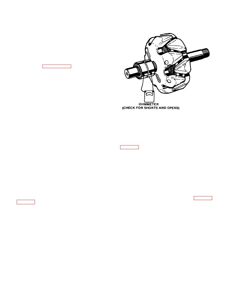
Figure 7-2. Checking rotor winding.
(6) Remove two screws (22), lock washers
shorted windings; a reading below specified value
(23), insulated screw (24), insulator (25),
indicates excessive resistance.
brush and holder (26), brush spring (27),
and regulator (28).
An alternate method is to check the resistance of the
field by connecting an ohmmeter to the two slip rings
(7) Only as necessary, remove the terminal
package (29) and bearing (30) from slip
value, the winding is shorted; if above specified value,
ring end frame (31).
the winding has excessive resistance. The specified
resistance value is determined by dividing the voltage by
(8) Remove three screws (32), retainer (33),
the specified current.
The winding resistance and
inside collar (34), bearing (35), and grease
ammeter readings will vary slightly with winding
slinger (36) from drive end frame (7).
temperature changes.
c. Component Testing.
Test
the
(2) Diode trio check .
The diode trio is
components as described below.
checked while removed from end frame assembly.
Connect an ohmmeter having a 1/2-volt cell, and using
(1) Rotor field winding checks. To check for
the lowest range scale, to the single connector and to
opens, connect an ohmmeter to each slip ring as shown
one of the three connectors as shown in figure 7-3.
in figure 7-2. If the ohmmeter reading is high (infinite),
Observe the reading. Then, reverse the ohmmeter leads
the winding is open. Connect the ohmmeter from one
to the same two connectors. If both readings are the
slip ring to shaft. If reading is low, the rotor winding is
same, replace the diode trio. A good diode trio will give
grounded. The winding is checked for short circuits or
one high and one low reading. Repeat this same test
excessive resistance by connecting a 12-volt battery and
between the single connector and each of the other two
ammeter in series with the edges of the two slip rings.
connectors. Also, connect the ohmmeter to each pair of
Specified field current at 80F (26.7C) is 4.0-4.5 amps.
the three connectors. If any reading is zero, replace the
An ammeter reading above the specified value indicates
diode trio
7-3


