TM 5-4310-354-14
(2) If the slip rings are dirty, they may be
cleaned and finished with 400 grain, or finer,
polishing cloth.
CAUTION
The rotor must be rotated when
cleaning or finishing the slip rings so
that they are cleaned evenly.
Cleaning by hand without spinning
the rotor may result in flat spots on
the slip rings causing brush noise.
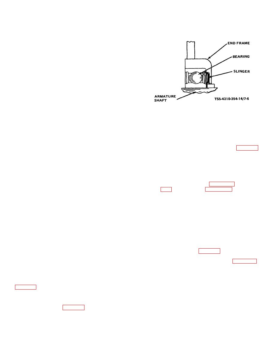
TS5-4310-354-14/7-6
Spin the rotor and hold polishing cloth
against the slip rings until they are clean.
Slip rings which are rough or out of round
Figure 7-6. Drive end bearing assembly.
should be trued in a lathe to 0.002 inch
(0.051 mm) maximum indicator reading.
a tube or collar that just fits over the outer
Remove only enough material to make the
race. Fill cavity between bearing and
slip rings smooth and round. Then, finish
retainer plate with lubricant equal to
with 400 grain, or finer, polishing cloth.
Delco-Remy No. 1948791.
Blow away all polishing dust with clean,
dry compressed air.
(2) Reassemble inside collar (34, figure 7-1)
and a new retainer plate (33) if the felt
(3) Inspect brushes for cracks, chips, and
seal is hardened, worn, or otherwise
excessive wear. Replace the brush and
defective. Attach with three screws (32).
holder assembly when brushes are worn
to less than 1/4-inch (6.35 mm).
NOTE
(4) Inspect brush springs for cracks, breaks,
At reassembly refer to figures 7-3 and
distortion, or any other defect.
reassembly order of parts.
(5) Inspect bearings for freedom of rotation,
any gritty action, wear, or any other defect.
(3) Reassemble a new bearing (30) in slip
ring end frame (31) using a flat plate over
(6) Inspect rotor bearing journals for wear, scoring,
the bearing and press in from the outside
pitting, or any other defect.
toward the inside of the frame until bearing
is flush with outside of end frame. Support
(7) Check all parts for cracks,
breaks,
the inside of the end frame with a hollow
distortion, damaged threads,
burned
cylinder to prevent breakage of the frame.
insulation, or any other defects.
Use care to avoid misalignment of
bearing. Reassemble terminal package
(8) Repair of the alternator, other than that
(29), refer to figure 7-4, for order of parts.
detailed above, is limited to the
replacement of defective parts, or the
(4) Reassemble regulator (28, figure 7-1),
entire assembly.
brush spring (27), brush and holder (26),
insulator (25), insulated screw (24), two
e. Reassembly.
Reassemble the alternator
lock washers (23) and two screws (22).
assembly in the reverse numerical sequence shown in
(5) Reassemble capacitor (21) into capacitor
bracket (20) ; attach with screw and lock
(1) Reassemble grease slinger (36) and
washer (19), lock washer (18), and screw
bearing (35) into drive end frame (7) as
(17).
shown in figure 7-6. Press bearing in with
7-6


