TM 5-4310-362-14
CHAPTER 4
TECHNICAL PRINCIPLES OF OPERATION
4-1.
CHAPTER OVERVIEW
This chapter contains a description of how the air compressor works.
Section I describes the operation of the whole system. Section II describes the operation of the individual components.
Section I. AIR COMPRESSOR SET
4-2.
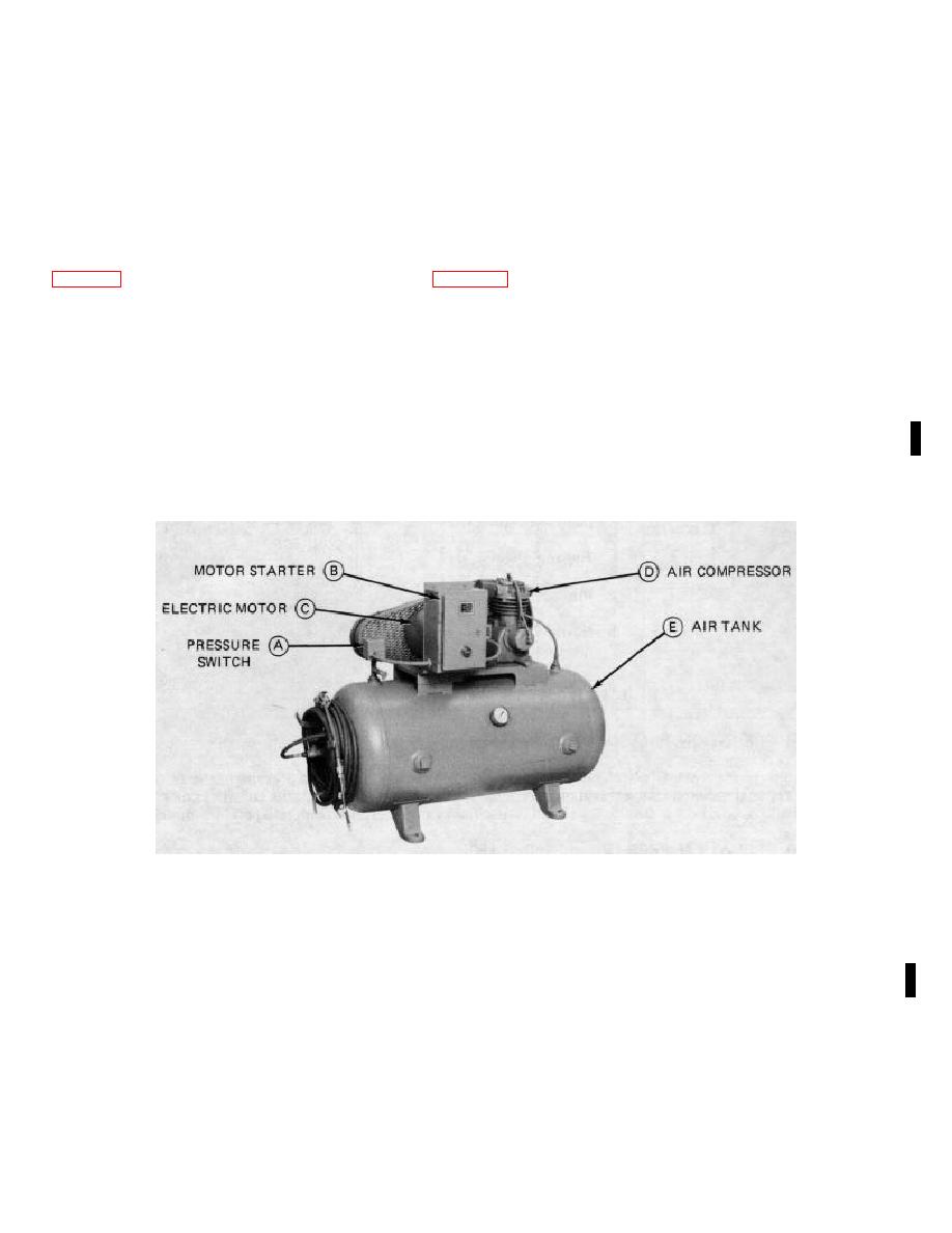
AIR COMPRESSOR SET FUNCTION
A
PRESSURE SWITCH. The switch is wired in series with the motor. When pressure in the tank drops below 160
psi, the switch doses and starts the motor. When pressure in the air tank rises above 180 psi, the switch opens and
stops the motor. The switch on the Model 20-911 compressor also controls the unloading of the compressor.
B
MOTOR STARTER. The starter protects the motor from a current overload. Current overload causes the starter to
break the circuit and stop the motor to prevent it from burning out.
C
ELECTRIC MOTOR. The electric motor drives the air compressor D. An electric motor has the advantage of being
easily turned on and off so that the compressor does not have to be run when no air is being drawn from the air
tank E.
D
AlR COMPRESSOR. The air compressor compresses the air by means of pistons. Its operation is similar to a
gasoline engine except that the power to drive the pistons is supplied by the electric motor.
E
AlR TANK. Th e air tank acts as a reservoir for the compressed air. It also dampens pressure fluctuations which
you would get if you took the compressed air directly from the air compressor.
Change 1 4-1


