TM 5-4310-368-14
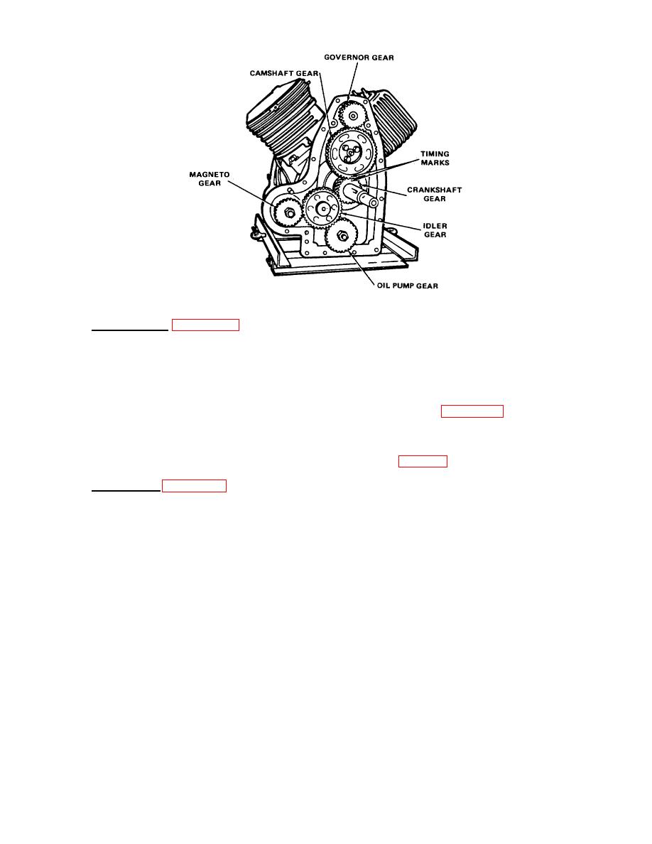
Figure 6-31. Idle Gear and Shaft
I.
Cylinder Heads. (Figure 6-13)
(1)
Position cylinder head and new cylinder head gasket over right cylinder bank.
(2)
Align cylinder head and gasket with cylinder block and install two 5/16-18" x 13/8" screws, fifteen 5/16-
18" x 1-1/4" screws and seventeen 5/16" lock washers.
(3)
Tighten screws to 24 Ib-ft torque. Use tightening sequence shown in Figure 6-32.
NOTE
Long screws are to be installed in positions 20 and 21 in Fig. 6-32.
m.
Air Shrouding. (Figure 6-12)
(1)
Install left lower cylinder shroud.
(2)
Install right lower cylinder shroud.
(3)
Position flywheel shroud over front of engine. Align bolt holes in flywheel shroud with holes in engine
cover and secure flywheel shroud to engine with six 5/16-18" screws and lock washers.
(4)
Install right heat deflector and side shroud cover.
(5)
Install three 1/4-20" screws and lock washers into side shroud cover.
(6)
Install left heat deflector.
(7)
Install right rear shroud cover.
(8)
Install three 1/4-20" screws and lock washers into right rear shroud cover.
(9)
Install left rear shroud cover.
6-26


