TM-5-4310-389-14
m. Rear bearing removal. Move rotor leads away from the bearing puller contact area. Carefully remove bearing. Do
not damage the threads at the end of the shaft with the puller. This completes the disassembly of the alternator.
Clean all parts being reused with solvent (O-T-62).
n.
Replace bearing.
o.
Slide slip ring onto shaft.
1.
Guide the rotor leads through one of the oval passages in the slip ring assembly. Ensure the oval passage is in
line with groove in rotor shaft.
2.
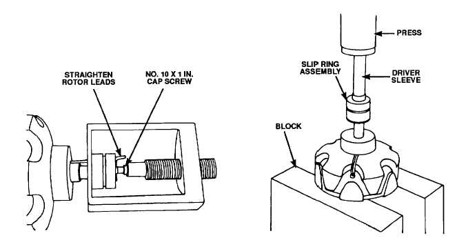
Place the rotor on a press (figure 4-67) and, using an installation sleeve with a diameter that clears the leads,
press the slip ring assembly onto the rotor shaft.
3.
Solder the rotor leads to the leads on the slip ring. Trim all excess lead extending above the soldered
connections.
p.
Solder end of rotor leads to slip ring terminals.
q.
Placing the rotor/front housing assembly on a press, press front bearing (9) onto the rotor shaft and into the front
housing (8).
r.
Place diode (20) into rear housing.
s.
Insert insulators into alternator terminal studs; replace lock washers and hex nuts.
Figure 4-66. Removing Slip Ring Assembly
Figure 4-67. Installing Slip Ring Assembly
4-95


