TM-5-4310-389-14
5-8
CYLINDER HEAD SET (ENGINE).
DESCRIPTION
This task covers: Test. Repair.
INITIAL SETUP
Tools:
Tools (Contd):
Clamping stand No. 003-0562
Special milling cutter, hard
Clamping plate No. 003-0794
metal No. 003-0652
Valve spring compressor
Arbor assembly
No. 0093-0504
Inlet No. 003-0620
Cutting device No. 003-0426
Exhaust No. 003-0441
Turning fixture No. 003-0621
Cutter for valve seat ring,
Guide mandrel No. 003-0764
inlet exhaust No. 003-0784
Mandrel for turning off the valve
Arbor assembly No. 003-0453
seat rings on lathe No. 003-1234
Reamer No. 003-0452
drilling device No. 003-0649
Puller No. 003-0434
Pilot pin with drilling bushes
Vinear
No. 003-0650
Equipment conditions:
Materials/parts:
Cylinder head removed (paragraph 4-15).
Cloth, Lint-free, item 9 Appendix E
TEST
a.
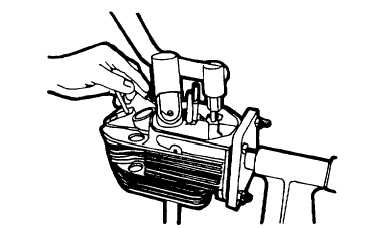
Bolt the cylinder to the swivel clamping stand (figure 5-70). Dismantle both valves with springs, valve rotator, and
washer (use clamping stand No.003-0562 with plate No. 003-0794 and valve spring compressor No. 003-0504).
Figure 5-70. Cylinder Head Bolted to Swivel Clamping Stand
5-43


