TM 5-4310-393-14
e.
Torque cap screws (Figure 5-1, Items 5 and 9) to 51 6 lb -ft (70 Nm) and cap screws (13) to 22.13 Ib.-ft (30
Nm).
5-6 2. FUEL INJECTION PUMP.
This task covers: A. Test B. Remove C. Install D. Adjust
Tools:
Materials/Parts:
Tool Kit, General Mechanic's Set
Diesel Fuel NSN 9140-00-268-5294
Shop Equipment, Automotive
Lubricating Oil
Maintenance and Repair
Shim Set
Testing Device for Injection
Equipment Conditions:
Equipment 60462800
Fuel Lines and Check Valve Removed
Dial Gauge, 61208700
Spill Device, 66503001
Socket Wrench, 30 mm, 66833500
Special Wrench, 60600000
A.
Test.
1.
Testing the Fuel Injection Pump.
NOTE
Perform this test both before removal
of the injection pump from the engine
and after re-installation.
WARNING
DEATH OR SERIOUS INJURY COULD
OCCUR IF FUEL IS NOT HANDLED
CAREFULLY. USE IN A WELL
VENTILATED AREA AWAY FROM
OPEN FLAME, ARCING EQUIPMENT,
IGNITION SOURCES, HEATERS, OR
EXCESSIVE HEAT. ENGINE MUST
BE
TURNED
OFF
AND
COOL
BEFORE
REFUELING.
ALWAYS
STORE FUEL IN PROPER, MARKED
CONTAINERS. DO NOT SMOKE.
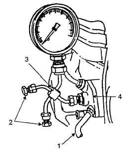
FIGURE 5-2. INJECTION PUMP TEST
a.
Connect fuel hose (Figure 5-2, Item 1) from fuel tank to injection pump (4).
b.
Ensure the extra fuel device button is not pulled out If the button is extended, push it back in.
c.
Connect testing device 60462800 (3) to injection pump (4). Ensure side connections (2) are tightly
capped.
d.
Loosen the pressure gauge connection and crank the engine until trapped air is removed from the
system.
e. Tighten pressure gauge connection.
CAUTION
Do not scratch or mar mating surfaces of pump body or cover. The fuel injection
pump may leak or otherwise malfunction after reassembly.
5-8