TM 5-4310-393-14
C.
Install.
1.
Installing the Fuel Injection Pump.
a.
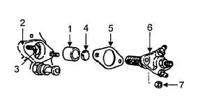
Install tappet (Figure 5-4, Item 1)
Into crankcase (2).
b.
Turn engine by hand until tappet (1)
reaches the lowest point of cam.
c.
Position throttle control hand lever
so that governor lever slot (3) lies exactly in the center of
the tappet bore.
FIGURE 5-4. FUEL INJECTION PUMP-INSTALLATION
d.
Install plate (4) with the flat surface toward injection pump (6). Place appropriate shims from shim set
(5) on crankcase studs.
f.
Position injection pump (6) so that control sleeve pin is aligned with the slot in the governor lever.
g.
Insert injection pump (6) taking care not to move the control sleeve pin out of alignment.
NOTE
No resistance should be felt until the pump is within 0.160 inch (4 mm) of the
crank-case, then a resistance due to initial load of plunger spring can be felt.
CAUTION
Do not tighten pump if not seated properly. Damage to pump, governor lever, or
engine could result if improperly installed.
h.
Using hand pressure, insert injection pump (6) fully into crankcase (2) and install two hexagon nuts
(7).
I.
If the pump does not seat properly, the control sleeve pin of injection pump has not entered the slot
(3) in the governor lever and steps f through h should be repeated.
D.
Adjust.
CAUTION
When adjusting timing, give special attention to rotation of engine. Timing can be
accomplished only when engine is rotated correctly. Correct rotation is counter-
clockwise when facing the flywheel.
1.
Preliminary Steps. Prepare for adjustments of the injection pump as follows:
a.
Remove obstructions to expose engine flywheel.
5-10


