TM 5-4310-393-14
b.
Connect a gravity feed fuel hose to the injection pump.
c.
Place hand throttle control lever in full throttle position and center the pump control fork in relation to
the bore in the crankcase.
NOTE
It may be necessary to loosen the
lock nut with 30 mm socket wrench
66833500 and turn the extra fuel
button slightly, using special tool
60600000, adjusting wrench for extra
fuel device.
d.
Hold the extra fuel device and
tighten the lock nut to establish a reference point
e.
Install the injection pump without
shim but using two paper gaskets
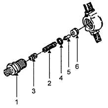
FIGURE 5-5. DELIVERY VALVE HOLDER
f.
Turn the crankshaft so that the cam is at its lowest point
g.
Unscrew delivery valve holder (Figure 5-5, Item 1) and remove spring (2), filling piece with shims (3),
copper washer (4), delivery valve (5), and valve body (6).
h. Insert
copper
washer
(4)
and
delivery valve body (6) only into spill device 66503001.
I.
Thread
spill
device
66503001
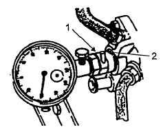
(Figure 5-6, Item 1) into injection pump with spill pipe (2)
in the up position, and then secure in place.
j.
Install dial gauge 61208700 with
adapter pin 1.64 inch (41 mm) long attached, into spill
device and pretension approximately 1 mm (one rotation
of dial indicator hand).
k. Remove fuel shutoff clamp from fuel
hose.
FIGURE 5-6. FUEL PUMP AND SPILL DEVICE
NOTE
Fuel emerging from the spill pipe on spill device 66503001 must be bubble free.
2. Adjustment of Delivery End. Delivery end of the fuel injection pump is adjusted as follows:
NOTE
The position of TDC (Figure 5-7, Item 2) and end of delivery (3) is marked on the
flywheel (1). The corresponding alignment mark (4) is on the right upper side of
the crankcase.
5-11